What exactly would it "prove"? That a copy to a different medium / format can be different than the original? That we already knew.
I think it'd just 'prove' that the ADCs and DACs used weren't transparent enough, if the two were distinguishable. Let's face it the likelihood is that the DAC its played back on has opamps within. Perhaps the ADC too. No news there either. But I do believe with optimized converters there would be nothing to distinguish the two.
The "Slew Rate vs. Input Level" graph on the LT1358 datasheet was a complete surprise to me---that its touted 600 V/uSec was really only ~150V/uSec with a typical 1 volt RMS signal. Is the same true with other opamps with high quoted slew rates?
Let me see if I get the flow here.
Morry rolled an opamp and reports he heard a difference.
So the issues become;
Did he really hear a difference?
Is this difference a change in preferred sound or accuracy?
Is the difference due to the actual opamp change or some other issue?
Is there a measurable difference in standard measurements such as THD?
As I expect there is not a significant diffference in THD, is there a measurement that tracks the perceived changes?
Seems to me arguing about if or what changed with partial information is not completely useful.
Now as to a real change in using opamps is that for some strange reason they seem to fail when soldered into place with my Weller soldering gun! 🙂
A friend of mine once thought they could repair a Samsung TV with bad caps using a big soldering gun and a roll of acid core solder. 🙂
Where can you buy lt1358 chip? Internally it is very different than what I normally use.
Superceded?
Superceded?
Last edited:
Digikey. PM me and I will send you some that are just slightly over my noise spec.Where can you buy lt1358 chip? Internally it is very different than what I normally use.
Superceded?
The LT1358 sure is fast! Also has higher noise and MUCH HIGHER distortion specs than most of the other super opamps. A little on the expensive side, as well---->$7 each!
Digikey. PM me and I will send you some that are just slightly over my noise spec.
Ah-ha! I was looking at Mouser.
PM sent
Jan, SY, and I did the op-amp mic thing before and all was fine and yes I was there.
There is so much talk by industry professionals on both sides of this, who do you believe?
We even put it on line:
https://linearaudio.net/sites/linea...kHz) recorded Wurcer mic preamp nov 2011.flac
For good measure, here's the applause:
https://linearaudio.net/sites/linea..._recorded_with_Wurcer_mic_preamp_nov_2011.wav
Venue was SY's residence.
BTW, the interesting thing with a growing ignore list is that a whole parallel thread seems to develop that you haven't have to read! 😀
Jan
Then there's the whole confusion on the difference between small-signal and large-signal specs in the context of slew rate, and what exactly is a 'slow' or 'fast' amplifier.
Bruno worked it all out:
http://linearaudio.net/sites/linearaudio.net/files/volume1bp.pdf
I don't expect many of the slew-rate obsessed pundits here to read it - after all, it is hard to interest someone in something when his success and well-being depends on his ignorance of the subject.
But even if one lurker out there picks it up, that's worthwhile for me.
If you don't want to educate yourself on feedback, skip to page 7: 'Open loop bandwidth as a measure of speed'.
Have fun.
Jan
Last edited:
Well, nobody is doubting the amount of testing.
However, we might get curious as to applying it for our needs, that might differ somewhat.
However, we might get curious as to applying it for our needs, that might differ somewhat.
The part that does not line up with your thinking is that every time I used a faster device, be it in a design of my own or a modification of an existing unit that same result happens. This has played out since the early 90's when I was exposed to this philosophy.
Robert: You are due a lot of slack due to your pricing model and returns policy, but this is comedy gold. You do really need a component guru like JC found to make the story better.
Hey guys. Next time you're picking on me, at least have some balls and do it like the gentleman above. Allusions to ignore lists and such are for sissies. 😉
I never put anyone on an ignore list, prefer to keep debating... and even then it is just a debate, even if it gets a bit heated when the participants cant convince the other their view is wrong...😀
As promised, here is the mic pre designed by Scott. I'm just the draftsman 🙂
Jan
Much thanks to both Scott and Jan for providing another DIYaudio Aha-erlebnis. Nice how this whole thing balances on the gate of Q1. Smart way of creating an artificial ground in a single supply balanced output with a passive two component servo. Something to remember for future misappropriation. The op-amp used looks great too and not too expensive. I have a question which I am sure further study and a bit of calculation could solve but I am lazy.
At DC, there is a 1:100 impedance mismatch between the inputs of U1:B. Doesn't that lead to a DC error and additional distortion? Or does it do so but does not matter?
Robert: You are due a lot of slack due to your pricing model and returns policy, but this is comedy gold. You do really need a component guru like JC found to make the story better.
Well bill, not everyone that sells something is a charlatan. At his prices, it looks to me more like a "service to the community" than a method of "get rich quick".
One day I'll tell you the story of how I bought a "horizontal folded dipole yagi" antenna from a gentleman making them in England and how it actually worked as described, not to mention that it was less expensive (shipping included) than if I were to build it myself from Home Depot materials.
For now I'll just let you know that when it comes to RF and radio, there are a lot of charlatans peddling "miracle antennas", with the claim that they are smaller and work better than their larger classic counterparts.
It all felt apart a few years ago when a Chinese gentleman published a paper with mathematic proof that, for a given wavelength lambda, you cannot build within a sphere of diameter lambda/2 a more efficient (from total radiated power pov) antenna than a lambda/2 dipole. Pretty much like in audio, there was furious denial of everything - Lorentz, Maxwell, name it they denied it one way or the other. And much grief caused by the realization that you can't beat good old dipole no matter what you do (except an even larger antenna of course lol).
Dunno about that, you can get very good results with a magnetic loop antenna, albeit very high Q = ultra tight bandwidth...
I used to work developing cellular radio. We saw many of those charlatans. Luckily we had access to proper test facilities so was easy to prove if they worked. Fractal antennas was a rich vein of BS, but luckily (as you know) antennas is a field where Maxwell works very well in the design.
Previous to that, trying to get good FM coverage in my student digs I did spend good money on an indoor antenna, only to realise later that 2 lengths of copper pipe did a much better job.
Previous to that, trying to get good FM coverage in my student digs I did spend good money on an indoor antenna, only to realise later that 2 lengths of copper pipe did a much better job.
Much thanks to both Scott and Jan for providing another DIYaudio Aha-erlebnis. Nice how this whole thing balances on the gate of Q1. Smart way of creating an artificial ground in a single supply balanced output with a passive two component servo. Something to remember for future misappropriation. The op-amp used looks great too and not too expensive. I have a question which I am sure further study and a bit of calculation could solve but I am lazy.
At DC, there is a 1:100 impedance mismatch between the inputs of U1:B. Doesn't that lead to a DC error and additional distortion? Or does it do so but does not matter?
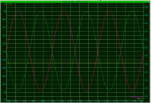
I had exactly the same reaction when I first saw that! I then threw it into the simulator, and there is a bit of offset generated (quarter of a volt or so), but since it is all AC coupled out, it doesn't make a difference to the final result.
Legend: GREEN and RED are the two outputs, YELLOW is non-inverting input of U1:B, PINK is source of Q1.
Edit: that '2 component servo' as Vacu called it is a seemingly very simple thing, but who would have thought of doing it that way? I bet 99.9% of us would have had our reaction - offset! It takes someone with the insight and out-of-the-box thinking like Scott to go ahead with it and do it in this circuit. Chapeau.
And the dual bootstrap to neutralise any and all of the FET's (nonlinear) capacitances is also very clever. Sorry I only have one chapeau ;-)
Jan
Attachments
Last edited:
Robert: You are due a lot of slack due to your pricing model and returns policy, but this is comedy gold. You do really need a component guru like JC found to make the story better.
Erm.... JC uses several. So far I have measured types of solder for distortion, resistors for distortion, capacitors for vibration, humidity, burn in and distortion, switch and relay contacts, transformers for noise generation and pass through and currently working on loudspeaker cables.
No "story" just actual measurements. Some of which have had "legs" and many results are used by some folks.
Now designing a preamp by personal preference is fine. Those round record thingies were mostly standardized by listening preference and standards with numbers assigned accordingly. The interesting result is that a lot of other folks seem to agree with M.
Jan on the other hand always seems to go by measurements so of course he is always wrong when he does so! ( 🙂 ) Pure coincedance others seem to agree with his results.
Now another problem with opamps is that they are coming in even smaller cases! Not as easy to use as those nice octal sockets.
Well there is only one who got his initial on the product!
You missed 'resistors for vibration' off your list. 😛
So what is the 'Ed way'? (sorry can't handle Edward). Measure to death then just glom something in and see if FoH complain?
You missed 'resistors for vibration' off your list. 😛
So what is the 'Ed way'? (sorry can't handle Edward). Measure to death then just glom something in and see if FoH complain?
Last edited:
- Status
- Not open for further replies.
- Home
- General Interest
- Everything Else
- What is wrong with op-amps?