Fractal antennas was a rich vein of BS,
😀
We can better them, let's propose gilded feed cables "to improve SSB audio quality" 😀
Back to Scott's preamp. One may notice that no matter how good these things "opamps" are, there's still place for a discrete FET, eh? 😉
Now another problem with opamps is that they are coming in even smaller cases! Not as easy to use as those nice octal sockets.
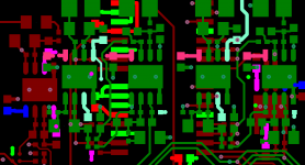
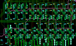
The 1.27mm pitch soic packages are good, go nicely with 0603 and 0805 discrete's... the really small packages are a bit more taxing but allows more to be packed into whatever space you have, the pic below shows 0.5mm pitch op-amps and associated discrete's... course you really have to use laser drilled vias (o.1mm hole).
Attachments
Back to Scott's preamp. One may notice that no matter how good these things "opamps" are, there's still place for a discrete FET, eh? 😉
Der obviously... nest you'll be telling us day follows night😛
Jan, thanks for the reply, I didn't see coupling caps on the schematic, hence my question about dc offset. As to distortion, is this opamp especially resilliant when it comes to impedance mismatch? Would be another good reason to like it. As to the hats off for Scott: the design is like a balerina balancing on one toe and the whole thing strongly appeals to my sense of beauty. Sometimes engineering is art.
Well there is only one who got his initial on the product!
You missed 'resistors for vibration' off your list. 😛
So what is the 'Ed way'? (sorry can't handle Edward). Measure to death then just glom something in and see if FoH complain?
I did test resistors for vibration. It should come as no surprise the result was the nil.
The "Ed way" is to check to see if claims of magic parts have any measurable basis. For example I tested many types of solder for very low levels of distortion on a PC card with 200+ joints. As there are folks who report hearing the difference in just a single test joint, my tests did not verify that. Perhaps slightly surprising was that even at that many joints there was no significant difference in my tests.
Now my latest bit with loudspeaker wire makes enough of a difference even the guys who have to pay the bills could hear the difference.
Resistors can make a difference and particularly some "Audiophile" types that do have higher distortion and will color the sound.
Capacitors for the most part have low enough distortion as they usually are no longer in the signal path. But used as a DC blocking capacitor vibration or microphonics may be an issue. In power supply use there are lots of internal inductance and resonance issues.
Switches should be bi-furcated crossbar contacts with a gold plating and not coupled to the relay coil's magnetic field. They also should not have magnetic material in the circuit path.
Now transformers are way too complicated for a short answer.
The more tools we have and the better we know them, the more useful.
Last edited:
The 1.27mm pitch soic packages are good, go nicely with 0603 and 0805 discrete's... the really small packages are a bit more taxing but allows more to be packed into whatever space you have, the pic below shows 0.5mm pitch op-amps and associated discrete's... course you really have to use laser drilled vias (o.1mm hole).
Ah... Marce,
Those plots are beginning to look like Hollywood's idea of an LSD trip! Anyways how do you solder those tiny chips with a Weller soldering gun? They are getting to be smaller than the tip.
I remember Martin Colloms complaining about lead free solder. Now in the early days there was a lot wrong with lead free as the soldering processes were sorted but that was some super loopy from him.
Back to Scott's preamp. One may notice that no matter how good these things "opamps" are, there's still place for a discrete FET, eh? 😉
You need the impedance transformation i.e. 5G Ohm bias return to move the KT/C noise far below the audio range. If you remember the derivation of KT/C noise for a capacitor it's an integral as R goes to infinity, so you make R as big as possible. Even a JFET has Ib so there is a limit.
The normal circuit simply uses a JFET phase splitter with 2.2K resistors, the dynamic range for < 1% THD is limited and the bias has a sensitive tweak to minimize 2nds. There is also a charge pump or flyback converter to make the 40-60V bias. This circuit does 100hr. on a 9V battery and has low THD to almost 16V p-p out (more than you would want?).
I suspect a professional recording engineer would be put off by not having the soft compression at lower output level because they are used to it.
What exactly would it "prove"? That a copy to a different medium / format can be different than the original? That we already knew.
A more lucrative experiment would be to compare copies of the same generation. Since there's no way to go back in time and install a digital recorder at the venue..... you're left to copying Jan's tape to a second Nagra and to a digital recorder then compare the results.
Prove?
It might show a whole lot?
Some seem to think that digital exceeds analog in all regards, at least any that matter. So, in "theory" at least, a digital copy ought to be indistinguishable from the original.
I agree a very good thing to try would be a feed from the same mic pair to an analog recorder and a digital.
There's no "proof" of anything here, just areas to consider and explore. Proof takes a whole lot more effort.
The main point is that everything is NOT EQUIVALENT - opamps, microphones, analog recorders, digital gear, even resistors and capacitors, and very likely wire and even solder. What degree the non-equivalence exists is the basis for all the different viewpoints.
So, one might start to get closer to the "core" by first finding those non-equivalences that are somewhat easier to find, and noting them, then moving down the "food chain" toward the plankton and away from the large sea-going mammals like whales... this is one that I suggested to consider.
(let's recall now, that a lot of people seem to say that they do NOT hear differences in DACs, DAC chips, opamps used AFTER DAC chips, and that digital is a "better" than analog recording/playback medium)
I remember Martin Colloms complaining about lead free solder. Now in the early days there was a lot wrong with lead free as the soldering processes were sorted but that was some super loopy from him.
It's the flux I hate, now even more. Someone clever loaded up our heated ultrasonic bath with 60/40 iso to water instead of 40/60 and it caused an explosion and fire which got anything but DI water banned.
I remember all the orange oil pens arriving to clean things. For a while R&D and the production line has a nice orangy overtone.
It's the flux I hate, now even more.
I hate what it does to BGA solder joints. Especially for large BGA packages that need to go through numerous, severe thermal cycles during the product lifetime.
OTOH it "creates jobs, good for the economy!" 😀
in the early days of unleaded getting micro-BGA to stay on boards was a challenge. I am glad I was not on mobile phone production at the time...
Regarding this LT1368 IC and its near relatives: I do have a story.
Back about 15 years ago, we took the Parasound JC-1 power amps to the CES and we 'borrowed a speaker system that used its own active crossover. We used my CTC Blowtorch to drive it. However, my then CTC business partner, Bob Crump was unhappy with the sound, which was good, but not as good as we wanted. Bob pinned the problem down to the IC's in the active crossover that were respectable OPA 2134's (I'm pretty sure) and he and his associate (who worked at Motorola at the time) believed that changing the IC's to perhaps an LT1368 or something related would improve the sound, but of course we could do nothing at the CES itself. Later, Bob DID modify one of these active crossovers and it DID make a serious improvement in the sound. Now, are the OPA2134's a bad IC? Of course not, just not the best possible IC's for all aspects of audio processing. Look to the OPEN LOOP BANDWIDTH for the difference.
Back about 15 years ago, we took the Parasound JC-1 power amps to the CES and we 'borrowed a speaker system that used its own active crossover. We used my CTC Blowtorch to drive it. However, my then CTC business partner, Bob Crump was unhappy with the sound, which was good, but not as good as we wanted. Bob pinned the problem down to the IC's in the active crossover that were respectable OPA 2134's (I'm pretty sure) and he and his associate (who worked at Motorola at the time) believed that changing the IC's to perhaps an LT1368 or something related would improve the sound, but of course we could do nothing at the CES itself. Later, Bob DID modify one of these active crossovers and it DID make a serious improvement in the sound. Now, are the OPA2134's a bad IC? Of course not, just not the best possible IC's for all aspects of audio processing. Look to the OPEN LOOP BANDWIDTH for the difference.
Look to the OPEN LOOP BANDWIDTH for the difference.
Won't find it here typical Aol 10,000,000 would place open loop BW down below a Hz.
EDIT - Hang on a second am I reading that right, 40kHz GBW on the LT1368? 10dB Aol at 10k, good scenario for an effects box in a conventional feedback RIAA. 29nV too, probably can't do a DBT due to the noise difference.
EDIT - John you got the number wrong it's 1358 so open loop BW is 200Hz TYP.
Last edited:
Look to the OPEN LOOP BANDWIDTH for the difference.
OMG. Why do we have to read the same wrong s*** again and again and again!
- Status
- Not open for further replies.
- Home
- General Interest
- Everything Else
- What is wrong with op-amps?