You would need to build a series of individual PCB's optimized for each op-amp being tested with the ability to instantly switch between them. If output levels were equal you might still notice differences but i recon they would follow specs. Ultra low distortion op-amps might sound better (to some) but others who are used to a bit of distortion may well disagree.
If for an experiment, it depends on the question being asked. If the question is about optimized circuits, that would be one thing. If the question is about distortion levels smaller than some measured value for some generic circuit, then different circuits would violate the premise of the question.
Ed, yes, you'd want to bypass with something like a 100 nF ceramic (which is almost universally recommended, as close to the pins as possible) + 10 uF electrolytic.
But your point to the overall complicated nature of the interconnections is why real-world tests are needed.
Not quite so simple. Some 10 uF capacitors will still not be down to an ohm at 100,000 hertz. Some will. But paralleling capacitors is not quite so simple. They all drop in impedance until the internal inductance limits the drop. As there is often little damping resistance, resonances show up.
Just doing data sheet design or modeling can miss the build up of resonances.
Then there is the rather interesting issue of exact capacitor type. In the same manufacturer's family identical values (C, V, T etc.) will have quite different resonances if they are radial or axial.
Even given two resistors from the same production line with the same manufacturing day in a tapped up reel next to each other, there are measurable differences. Very very small on good parts but measurable. I don't think any other real parts are as well matched as resistors.
Now when we get to capacitors, part of the fun is that larger parts often have better measured parameters but are also bigger antennas for stray fields.
As you know there is no new knowledge once one leaves the university! ( 🙂 ) One rule of engineering set in stone is that an individual part of a system should be 10 times better than you need to be sure the system meets the design goals.
So if a deaf old coot can hear the difference with only 6 opamps that would put the design limits at .6 opamps! Probably lower for a true golden ears ego. BTY my shop's large door is 14 feet wide so I can get my ego in each morning. Some evenings it can leave via the mail slot.
P.S. Something like a OPA1642 has ~40 dB PSRR at 100 kHz,
I can't find PSRR vs frequency for the NE5532 (the darling of this thread). For the device to which Bonsai connected his external current source, the LM4562, PSRR is quite good: 55dB at 100kHz with 30V between the rails.
Jan, "THD" is merely the label that LTSPICE attaches to a number it computes during Fourier analysis.
What the computed number is, in fact, is the RMS average of the harmonics (omitting the fundamental).
The printed value "61.206% THD" in post #2279, is just the RMS average. I copied harmonics 2 thru 11 into Excel to show the calculation, see below.
So it is the harmonic spectrum of the half sine you showed?
Does that have any relevance to the performance of the circuit - I think not.
Jan
BTW my shop's large door is 14 feet wide so I can get my ego in each morning. Some evenings it can leave via the mail slot.
Your sense of humour keeps pleasantly surprising me, Sir Edward 😀
Jan
The half sine is the waveform of the current which the opamp injects into the power supply network. This becomes a voltage noise on the supply since the supply's impedance is not zero. This becomes an output (error) signal since the opamp's PSRR is not infinity.So it is the harmonic spectrum of the half sine you showed?
Does that have any relevance to the performance of the circuit
It's an answer to the question "What possible good can come of injecting a DC current into the output pin of an opamp?" You may feel the improvement is negligibly small.
I can't find PSRR vs frequency for the NE5532 (the darling of this thread). For the device to which Bonsai connected his external current source, the LM4562, PSRR is quite good: 55dB at 100kHz with 30V between the rails.
Having measured some it is between 50-60 dB at 100,000 hertz. The typical spec is 10uV/V at 1,000 hertz.
But getting an accurate measurement was a bit of a pain. I built a PC card using IC power amps to drive the rails of the DUTs. Layout to say the least got interesting to be sure I wasn't screwing up CMRR.
I did blowtorch this a bit way back, but the testing showed nothing out of the ordinary. The result was the important issues are layout, layout, component selection and layout.
Last edited:
I can't find PSRR vs frequency for the NE5532 (the darling of this thread). For the device to which Bonsai connected his external current source, the LM4562, PSRR is quite good: 55dB at 100kHz with 30V between the rails.
Yeah, it's such an old chip that no one has come through and published the full suite, unfortunately. JCX had a couple papers that talked about the interrelation between loop gain and PSRR/CMRR, but I can't find it quickly. But it's dominant pole compensation and similar GBW to the 1642, so ballpark it somewhat close?
Ed--yes, layout, layout, layout. I ride a bike to work, because a car is too small to fit my own ego. 😉
This becomes a voltage noise on the supply since the supply's impedance is not zero.
Nitpicking, that's not noise, not even close. It's bandwidth limited and strongly correlated.
Anyway, we use local decoupling for a purpose.
I dunno, Johan Hujising's book analyzes the 5534 (p.244-245) and saysBut [the 5534 is] dominant pole compensation and similar GBW to the 1642, so ballpark it somewhat close?
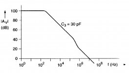
The HF compensation scheme can best be denoted by a capacitive feed-forward, coupled nested Miller compensation. The inner nest is compensated by C4 and the outer nest is compensated by C3. ... The nested Miller compensation would have been adequate in itself, if the bandwidth of the intermediate stage with the lateral PNP transistors Q8 and Q11 was not so low
To overcome this problem ... an HF feedfoward capacitor C2 has been inserted ... so that this stage is overbridged at high frequencies. However the overbridging changes the nested Miller compensation network at high frequencies ... This evokes a pole-zero doublet at 300 kHz where the gain is 30dB in the frequency characteristic as shown in the Figure [attached] ... This means the amplifier has a low phase margin, if operated at a feedback gain of about 30dB where the rolloff of the amplitude characteristic is larger than 20dB/decade. This makes the stability tricky in a tone-control circuit, where the feedback around the opamp is variable. Moreover, a slow settling component will distort the step response if used at a bandwidth above 300 kHz.
To overcome this problem ... an HF feedfoward capacitor C2 has been inserted ... so that this stage is overbridged at high frequencies. However the overbridging changes the nested Miller compensation network at high frequencies ... This evokes a pole-zero doublet at 300 kHz where the gain is 30dB in the frequency characteristic as shown in the Figure [attached] ... This means the amplifier has a low phase margin, if operated at a feedback gain of about 30dB where the rolloff of the amplitude characteristic is larger than 20dB/decade. This makes the stability tricky in a tone-control circuit, where the feedback around the opamp is variable. Moreover, a slow settling component will distort the step response if used at a bandwidth above 300 kHz.
Attachments
Thanks, Mark, learn something new every day. Given the differences in compensation between the 5534 and the 5532, is this doublet split?
I doubt it; if so then Hujising would have cautioned readers that tone control circuits work better with one than the other. And DIYA opamp experimenters over the past 30 years would have detected differences between the '34 and the '32 in listening tests. 🙄Thanks, Mark, learn something new every day. Given the differences in compensation between the 5534 and the 5532, is this doublet split?
Keep in mind the "difference" in compensation between the two is slight: the 5534 single opamp brings the compensation node out to its own I/O pin, while the 5532 dual opamp does not.
Mark, note that I published my results for the experiment asking the question, "How many IC op-amps (in this case OPA134) configured in unity gain needed to be placed in series before I can distinguish the chain from a straight wire, ears-only?"
The answer in that case was about 6. Test protocol, described in my article, was paired forced choice.
citation?
pdf?
_-_-
citation?
pdf?
I've been there, a major manufacturer of hi'ish end equipment socketed one of their pre-amps to show us how a change from copper to kovar lead frames sounded like shite. We heard nothing and we tried a lot even my wife tried, we heard jack-poop, nada, nothing. We were greeted with verbal abuse that would be censored here and nothing happened in the end they kept with the original design. I've done the 5% carbon film vs RN55C nothing either, so please stop thinking we don't do these tests.
The LCRMKIII started life out with 1n5819 1/2 wave rects. Schottky diode, should be pretty clean right? NO!
Once in a great while one would blow in the field. I got tired of this so I went with Hexfreds. Total game changer! I could much more easily hear the resistors.
If you can't hear the difference between a MF and CC resistor in the feedback position of the first gain stage of your preamp; you have more work to do.
I've been there, a major manufacturer of hi'ish end equipment socketed one of their pre-amps to show us how a change from copper to kovar lead frames sounded like shite. We heard nothing and we tried a lot even my wife tried, we heard jack-poop, nada, nothing. We were greeted with verbal abuse that would be censored here and nothing happened in the end they kept with the original design. I've done the 5% carbon film vs RN55C nothing either, so please stop thinking we don't do these tests.
Let me guess, they read about the change first and then noticed it sounded like shite?
I've compared the OPA2604's sound with and AD826 and the latter was far more detailed. That distortion correcting circuit shown in the OPA2604 data sheet seems to suck the life force out of the music. Buyer beware!Hi Gordy... try something like the OPA604 or OPA2604 if you have been used to valves. OpAmps do have their own sound, the fact that we seem able to pick up on these tiny differences always amazes me, but we do. The 604 has the "right" kind of distortion spectrum to sound pleasing I find.
Edit... whats wrong with opamps ? Nothing, it's the way they are implemented that's often wrong 🙂
Neither the OPA2604 (-110db THD; 11nv√Hz) nor the AD826(-78db THD; 15nv√Hz) are of state-of-the-art quality in terms of distortion OR noise. The OPA1612 (BP) or OPA1642 (FET) fare better by an order of magnitude. The 826 IS lightning-fast (350v/usec) but the others are all better than 20v/usec, which is more than enough.I've compared the OPA2604's sound with and AD826 and the latter was far more detailed. That distortion correcting circuit shown in the OPA2604 data sheet seems to suck the life force out of the music. Buyer beware!
- Status
- Not open for further replies.
- Home
- General Interest
- Everything Else
- What is wrong with op-amps?