If he uses CC for feedback resistors then the product price had better be reasonable!
It is. He's charging $300 for his phono stage, which in these days of products priced like a house, seems eminently reasonable to me.
It´s part of an article in linear audio vol.2 and Jan.Didden liberally made a free download available:
https://linearaudio.net/sites/linearaudio.net/files/LA Vol 2 Yaniger(1).pdf
If I get to pick the brand of resistors and the divider chain values pretty sure the distortion differences will reach the perceptable levels.
And I could pick an op-amp that possibly no one could make a passable phono stage out of.
I was helping an apps guy trying to measure THD on a new differential A/D driver on an AP. This was one of those circuits with external resistors. We couldn't get more than -130dB out of 0406 SMD resistors if we tried. I even had him play with the series and parallel tricks, so we concluded it really was the amplifier/instrument residual.
BTW I could not get any excess noise out of the brand of CF resistors we had lying around even at 10V DC.
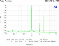
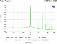
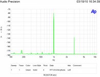
Attached are my distortion plots for a not very good carbon film resistor, a decent carbon composition resistor (but not the best), a decent metal film and a very good metal film resistor. 1,000 hertz is the test signal frequency as per my article in Linear Audio Vol. 1 It is nulled as best it can be for each resistor type. If the ability to null were perfect there would be no level. The leftover amplitude is from a bit of drift during the test interval. Base spreading is due to noise.
Attachments

Last edited:
And I could pick an op-amp that possibly no one could make a passable phono stage out of.
Click on image below to view at full magnification / without vertical compression
_
Attachments
Attached are my distortion plots for a not very good carbon film resistor, a decent carbon composition resistor, a decent metal film and a very good metal film resistor. 1,000 hertz is the test signal frequency as per my article in Linear Audio Vol. 1 It is nulled as best it can be for each resistor type. If the ability to null were perfect there would be no level. The leftover amplitude is from a bit of drift during the test interval. Base spreading is due to noise.
The worst looks like -100dB? You said perceptible. Level, remember the same claims are being made when used as a phono termination?
Attached are my distortion plots for a not very good carbon film resistor, a decent carbon composition resistor (but not the best), a decent metal film and a very good metal film resistor. 1,000 hertz is the test signal frequency as per my article in Linear Audio Vol. 1 It is nulled as best it can be for each resistor type. If the ability to null were perfect there would be no level. The leftover amplitude is from a bit of drift during the test interval. Base spreading is due to noise.
This is very helpful.
Thanks
-
Click on image below to view at full magnification / without vertical compression
_

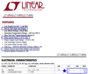
Obviously a very slow but very low supply current sensor buffer/opamp.
But there's something funny on this datasheet; 2.7kHz GBW and 1000V/us slew rate?
Or do they mean 1V/ms = 1V/micro-second? Sloppy.
Jan
Last edited:
1000V/us slew rate?
I think they were misled by ms instead of us.
Yes that must be it; I edited while you posted. Sorry 🙂
BTW tested today my CCS load for the direct drive amp Vas; 1.7mA at 4500V. Steady as a rock. The circuit, that is - I was jittery 🙂
Jan
BTW tested today my CCS load for the direct drive amp Vas; 1.7mA at 4500V. Steady as a rock. The circuit, that is - I was jittery 🙂
Jan
You are a braver man than I. Be careful- I don't want the women in my family heartbroken when I pass along the news of your demise.
Chimp reviewer inability to copy of the week
Dang Scott, your precision op-amps are only 1%! 😛
The $3000 CR-1 meets this need. Its continuously variable high- and low-pass filters (30–150Hz) use 1% precision JFET-input op-amps, and polypropylene film and foil capacitors to "optimize the audio system's spatial and spectral performance." The low- and high-pass circuits are built around two banks of precision Linkwitz-Riley filters that can be set for 12 or 24dB/octave via a front-panel switch.
Dang Scott, your precision op-amps are only 1%! 😛
Pretty sure it's one volt per millisecond a/k/a 0.001 volts per microsecond. The datasheet's scope photo of large signal step response appears to show the output slewing from 0V to +5V in 5 milliseconds. And the parametric search table on Linear Technology's website says the slew rate is 0.001V/microsecond, image below.
Hard to make a passable phono stage out of the LT1494.
Hard to make a passable phono stage out of the LT1494.
Attachments

It´s part of an article in linear audio vol.2 and Jan.Didden liberally made a free download available:
https://linearaudio.net/sites/linearaudio.net/files/LA Vol 2 Yaniger(1).pdf
Yah.
Thanks.
I have that issue.
My mind reading abilities seem to have waned over time. 🙄
Series? Terminating? Feedback loop? What are we looking at here?Attached are my distortion plots for a not very good carbon film resistor, a decent carbon composition resistor (but not the best), a decent metal film and a very good metal film resistor. 1,000 hertz is the test signal frequency as per my article in Linear Audio Vol. 1 It is nulled as best it can be for each resistor type. If the ability to null were perfect there would be no level. The leftover amplitude is from a bit of drift during the test interval. Base spreading is due to noise.
And define "best" when applied to the CC res. NOS CC's behave differently than currently made ones.
Last edited:
The worst looks like -100dB? You said perceptible. Level, remember the same claims are being made when used as a phono termination?
All shown tested the same 1-4/4-1 bridge method at 1/4 power. Raise the power, lower the frequency and the distortion rises. The scale is the same for all shown plots. It represents the relative results of each resistor type. It is not calibrated as to the distortion that would result in use as a voltage divider feedback resistor.
If I get energetic one day I may do the simple feedback usage at full power to get a calibration correction factor.
In use the worst resistor measured (Not shown) would give -19 dB third harmonic among the others re 1/4W at 100 hertz on that scale. However unless one were looking for coloration that bad of a resistor would stand out.
As to the claims that the differences are heard when used as a phono termination, the claims did match the measured results! However the mechanism or what is being perceived is a reasonable open question. I do have some ideas and am building test equipment that may provide some insight. Also note the differences in the plots besides just harmonic levels!
Last edited:
Go back and read my post #1554. The CC resistor in the feedback loop was a big step in addressing the "back of the concert hall" problem.
Series? Terminating? Feedback loop? What are we looking at here?
And define "best" when applied to the CC res. NOS CC's behave differently than currently made ones.
Best is lowest distortion. We are looking at the output of a ten resistor bridge in the 4/1 1/4 configuration. Two in series paralleled with a second series set for an equal value resistor but at 1/2 the voltage resulting in lower effects. One quad in the upper left to a single lower and the reverse for the other side of the bridge. Well covered way back in the blowtorch rope. (Too long to be a thread anymore.)
If you hold you mouse over the plot it identifies the resistor. All were current production at the time.
Go back and read my post #1554. The CC resistor in the feedback loop was a big step in addressing the "back of the concert hall" problem.
?? Adding a bit of distortion will increase the high frequency content. Distance has excess high frequency loss.
My standard response to these issues is who was the better painter Rembrandt or Picasso?
Vinyl sounds good and was developed with the primary test equipment being human ears. CD's have better measured distortion. Your choice as to what you prefer.
?? Adding a bit of distortion will increase the high frequency content. Distance has excess high frequency loss.
That would seem quantifiable, also there's the problem that the distortion goes down with increasing frequency (or at least you said so above). We could just ask Robert at what percentage of dissipation rating are the resistors in question being used. The last batch of high value NOS CC's I got were 80% high in value probably due to storage, another issue.
I ran across the CC thing with folks making fuzz pedals, though I have to admit the difference escaped me.
- Status
- Not open for further replies.
- Home
- General Interest
- Everything Else
- What is wrong with op-amps?