Yes please, let's know more about on chip resistors and processes....Scott ?.So.... what about those leetle teeny-tiny resistors on the chip?
Dan.
Yes please, let's know more about on chip resistors and processes....Scott ?.
Dan.
This is public record, I can't give details but we have products with resistors broken out on pins folks can measure for themselves. There's actually a lot of information here on some details of the materials/contacts.
https://www.google.com/patents/US6365482
This is public record, I can't give details but we have products with resistors broken out on pins folks can measure for themselves.
Maxim makes 0.035% matched resistive dividers in SOT-23 using thin film technology. Can't beat that with discretes, at any reasonable cost.
https://www.maximintegrated.com/en/...onverters/digital-potentiometers/MAX5491.html
Maxim makes 0.035% matched resistive dividers in SOT-23 using thin film technology. Can't beat that with discretes, at any reasonable cost.
https://www.maximintegrated.com/en/...onverters/digital-potentiometers/MAX5491.html
Doesn't say if they are laser trimmed. Yes, we use .005% resistors to make primary reference dividers for trimming in-amps, a small bag can be $1000.
They think they like the distortion sound of carbon and bakelite (there are better sounds).....never mind.Dan.
Guitarists also love 60-year old wood!
Last edited:
A friend has a mint original '58 Stratocaster...not quite 60 years but close.
Sounds damn good to me 😉.
Dan.
Sounds damn good to me 😉.
Dan.
Last edited:
Thanks, that was the kind of info I was asking, explains quite a lot.....There's actually a lot of information here on some details of the materials/contacts.
https://www.google.com/patents/US6365482
Dan.
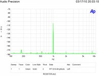
Attached are my distortion plots for a not very good carbon film resistor, a decent carbon composition resistor (but not the best), a decent metal film and a very good metal film resistor. 1,000 hertz is the test signal frequency as per my article in Linear Audio Vol. 1 It is nulled as best it can be for each resistor type. If the ability to null were perfect there would be no level. The leftover amplitude is from a bit of drift during the test interval. Base spreading is due to noise.
Can you share the supplier for this resistor?
I suppose impurities cause the others to behave as non linear resistors.
Attachments
You mean a CC resistor can determine how it is being used in a circuit, and behave differently? It somehow senses things other than its own terminal voltage difference and current flow? I am impressed: that is Module 1 in the Maxwell Demon Training Manual already covered.morinix said:They also behave differently in series than as terminators.
I'm not sure you understand. He was not making breakfast; he was measuring how pure is the sugar preferred by some people, by a method which does not require perfect sugar as a reference.Just use ONE spoon of sugar on your cereal. It will taste good that way.
yes, especially metal films but carbon can too.
ie MOVs , graphite etc.
small impurities and or oxides change linearity.
no demons. its an interesting subject.
it really gets fun if Tunneling or superconductive.
ie MOVs , graphite etc.
small impurities and or oxides change linearity.
no demons. its an interesting subject.
it really gets fun if Tunneling or superconductive.
no demons. its an interesting subject.
.
I think he was referring to attributing sentience to a resistor, it does not know how it is being used. Its behavior is determined by physics, if you read that patent you might appreciate the amount of effort and knowledge that goes into just one aspect of the dirty silicon.
But Scott those discrete resistors can let those bigger electrons through while those tiny chips can only pass the little ones! 🙄😀
But Scott those discrete resistors can let those bigger electrons through while those tiny chips can only pass the little ones! 🙄😀
I was around for some of the thin film development and in the beginning there was some secret sauce, we bought a small resistor network company to get their guru on staff. He formulated the "magic" sputtering targets and for a while only he could tweek the results. But in the end it was a lot of test wafers and a lot of work, I remember using the Quan-Tech to measure the excess while we were developing the platinum silicide contacts. Yesterdays tools.
Bear, I don't know what to tell you, what Ed's work does is complement datasheets (as those distortion tests aren't exactly in there), whereas the very data you're looking for is in the datasheets of the opamps. I suppose one could make a bridge circuit of different opamps and see what the differences are, but that would quickly become a wild goose chase where we're looking for residuals in the PPM or smaller.
Yes, the proof is in the pudding, which IS the output. However the heck you get it.
So all those things you're ostensibly wondering about (i.e. in-chip resistor linearity) are baked into the opamps ultimate performance. Dimitry recently linked Bruce Hofer's powerpoint presentation on high-performance analog, which talks about thermal modulation among other topics. Comes recommended.
If you want to tell if XYZ opamp is first audible, then some very careful tests need to be made. But how do you reconcile talking about many opamps being good enough for SOTA measurement equipment and yet somehow audibly different? That points to absolutely needing a heroic experiment to divine.
I agree there, daniel.
It is nearly impossible to reconcile the measurement equipment's use of "SOTA" opamps and the audibility considerations.
The answer I do not have - that's why at least I have an interest in exploring the issue, and trying to do some different tests in a (vain?) hope that something can be parsed out of all the measurements.
One thing that I can make a conjecture about revolves around the difference between the music/voice signal to the typical test/measurement signal. Is this a meaningful difference? This I don't know.
Actually, I would hope that what is found is exactly what you and others are saying - there are no audible difference - and that the differences that are being heard are actually due to one or more specific implementation factors (aka mistakes/errors) that are avoidable and can be determined in practice (aka calculated or empirically measured) and documented clearly.
For example, and only as a broad based example, perhaps it is essential (to NOT hear differences) that the local PS rail bypass caps need to be of a value specific to the circuit (aka not too little, not too much) and perhaps of particular characteristics.
But to determine this, one would first have to be able to reliably detect by ear AND measure by test equipment the differential.
So... assuming that my "string of 10" test circuit makes the issues extremely audible (keeping in mind now, SY's "6 buffer" experience), IF one could then make the issues substantially less, or completely inaudible by doing "x, y and/or z" THEN something real would have been determined.
Now, perhaps these things turn out to be well understood, and when implemented properly by "those versed in the art" obviates all the sonic issues - but that is only clear to those persons, otherwise nobody would be having this conversation, all circuits would incorporate the proper and well documented requirements, and the basis for all this would be moot.
Last edited:
Fwiw, and this is of course merely anecdotal, but the F5 circuit is pretty minimal.
When a friend built one up an asked for help with various issues (it has very low PSRR, that being one issue), along the way the resistors in series with the outputs were swapped out from very good WW to Caddock bulk film.
Substantial change in the overall impression of the sonic characteristics.
The Caddocks, of course are expensive.
I really didn't care one way or the other - they could have sounded the same or worse for all I care.
Let me put it this way. If you had heard the amp both ways and you were going to build one, you'd not even consider the wire wounds.
Is something going on up >250kHz? In the mHz range?? Not visible on a scope, anyhow. The increasing inductance might be a benefit... (unless it formed a resonant circuit...) So, why ought the WW not sound as good??
It's a two stage amplifier.
Since it wasn't my amplifier, and I did not have much hands on time with it, it was not possible to measure (to the extent of my equipment) anything. I would have liked to look at the harmonics in-band, but they change quite a bit with bias on the F5, so it would have been tough to draw any conclusions... unfortunately Rick became ill, passed away, and his amp build is to the winds...
I was around for some of the thin film development and in the beginning there was some secret sauce, we bought a small resistor network company to get their guru on staff. He formulated the "magic" sputtering targets and for a while only he could tweek the results. But in the end it was a lot of test wafers and a lot of work, I remember using the Quan-Tech to measure the excess while we were developing the platinum silicide contacts. Yesterdays tools.
Slightly OT: what do you think of a data sheet that contains following note:
"ADVANCE TECHNICAL INFORMATION
The product presented herein is under development. The Technical Specifications offered are derived from a subjective evaluation of the design, based upon prior knowledge and experience, and constitute a "considered reflection" of the anticipated result. "
The warning is nice, but they are selling this product already for years, and it looks like a way to cover their responsibility if anything.
This is an official data sheet of a reputed semi manu, who shall be mercifully remain undisclosed.
Jan
reputed semi manu, who shall be mercifully remain undisclosed.
Jan
Reputed or alleged? How do you subjectively evaluate an unrealized design?
Reputed or alleged? How do you subjectively evaluate an unrealized design?
They are selling the device. I queried their support because I thought the SOA graph wasn't quite right, and what do you say, the answer was, and I quote:
"Back to your question about FBSOA curve, the curve falls straight down from certain current to zero because of limitation of our test equipment. Definitely, it requires thermal analysis to make sure there is no thermal run away…."
So, in essence: "Yes, our SOA graph sucks, please do the legwork yourself if you don't want your stuff to blow up".
Jan
Reputed or alleged? How do you subjectively evaluate an unrealized design?
Easy if it is my design it is great no matter how bad it really is. If is someone else's then it is not as good. Well known in the home built loudspeaker arena.
As to the resistor question, if you hold your mouse over the image it will bring up the label. The good one is a Dale RN65.
But I think the axis of the world has tilted. DF and I agreed on something. 🙂
The other issue is test equipment tests what it is designed to do. It is that hammer line, everything is a nail.
Look at the resistor FFT's. The obvious is the distortion amplitude. Next is the base spreading. Then there is the fundamental null depth.
As with the chimp in the cage tale, what else is being shown?
. Well known in the home built loudspeaker arena.
I freely admitted on Earl's thread that I spent a lot of time designing a speaker in a totally reductionist manner and failed. That is measuring the impedance vs frequency and the output vs input of each driver and computing a perfect crossover for (at the time top of the line drivers) using a simulator. The result was to say the least a waste of time.
- Status
- Not open for further replies.
- Home
- General Interest
- Everything Else
- What is wrong with op-amps?