Here is a pic of the op-amps I am currently listening through. Folklore is that the AD MA332 became too expensive so they designed this.
Thick film hybrid! Oh the humanity. It actually just gets on with the job of amplifying.
No the MA332 was a rebrand of Raytheon 5534's the source vanished. I think I have two in a junk bin if you want them. Those boards are big, the 5534 schematic is certainly easy to find and I'll bet a literal discrete copy would be fairly OK.
Last edited:
TBH the phono does exactly what I want it to. No audible added noise and plays music. Never measured it but as the reviewers of the time claimed it was missing PRAT I suspect its nicely neutral. Oh and was £20 on ebay just needing a +/-15v supply. One of my better purchases in terms of enjoyment per £
TBH the phono does exactly what I want it to. No audible added noise and plays music. Never measured it but as the reviewers of the time claimed it was missing PRAT I suspect its nicely neutral. Oh and was £20 on ebay just needing a +/-15v supply. One of my better purchases in terms of enjoyment per £
I wonder in what order of importance, PRAT, toe-tapping, and micro-dynamics go?
There's a hotline for that kind of questions.
An externally hosted image should be here but it was not working when we last tested it.
To really stir the pot: Operational Amplifier Models : Operational Amplifiers - Electronics Textbook
To really stir the pot:
how about an older thread with a more colorful name:
http://www.diyaudio.com/forums/solid-state/3732-why-do-ic-opamps-suck-2.html

how about an older thread with a more colorful name:
http://www.diyaudio.com/forums/solid-state/3732-why-do-ic-opamps-suck-2.html
hey I'm moving over t that thread
http://www.diyaudio.com/forums/solid-state/3732-why-do-ic-opamps-suck-2.html#post32684
-
Want to bias your opamp further into class A? The LM334 is the easiest ticket. Tie V+ the op amp output. Tie V- to the negative rail. Tie the setting resistor from R to V-. Start with 1 or 2 milliamps.
Just wondering, why do people think this kind of setup is "bias into class A"? By any Class A definition, this is not true. The extra current has a completely different role than biasing the output stage in class A, it simply displaces half of the output stage transconductance so that the gm doubling distortions are reduced.
Just wondering, why do people think this kind of setup is "bias into class A"? By any Class A definition, this is not true. The extra current has a completely different role than biasing the output stage in class A, it simply displaces half of the output stage transconductance so that the gm doubling distortions are reduced.
You are right. What it does is simply turn off one output device making it into a single-ended output stage, making the thing that provides the external current into the se load impedance. Assuming the extra curent is sized to the max required output curent. If it is less, it just displaces the xover away from zero output. Something like a small-signal version of Douglas Self''s Cross-over displacement patent.
In Morinix example above, the LM334 is the se output stage load. That is an improvement?
Jan
Last edited:
No the MA332 was a rebrand of Raytheon 5534's the source vanished. I think I have two in a junk bin if you want them. Those boards are big, the 5534 schematic is certainly easy to find and I'll bet a literal discrete copy would be fairly OK.
Also still have a few RC5534's. And a few original Philips NE5534 with the famous Philips logo. Are these worth anything for collectors? 😎
Jan
I was proposing a string of 10 x 2 with the ability to A/B or A/B/X between the two.
(two separate and parallel stereo channels)
In the case of a unity gain set up, one might be able to set gains so that one could switch between a "wire" and string A or string B.
Measurements would be the first part.
The second part would be "casual listening".
Potentially with the box being passed around for impressions.
Anyone receiving the box could do properly controlled tests too.
Assumption: if the box goes to 10 people and 7 or 8 consistently pick "A" or "B" as best or say that the two sound different, or maybe all 10 say that, or perhaps it is 50/50 (essentially no result), then some information has been gathered.
There are a number of measurement tests that I could foresee using the board, and a number of variations in the subtle details of the circuit to try. Those versed in the art ought to find these variations self-evident.
Last edited:
So use them in a way that they aren't used in a real circuit, then run a test with no significance. Nice.
Those boards are big, the 5534 schematic is certainly easy to find and I'll bet a literal discrete copy would be fairly OK.
Missed your edit last night. I must admit to not knowing what SOTA was c 1990 for thick film hybrid. Certainly was about the same size as things I saw on a tour of a hybrid manufacturers around 1988 timeframe. But clearly not mil grade or super compact as needed to fit in a mid range audio product. Makes me want to rip it out and characterise it.
SY - you know, you have the ability to be condescending and pedantic.
No, actually nasty.
As a MODERATOR - and even though you post for your self, according to the rules - when you write in this manner, you give defacto approval for this sort of non-productive and hostile tone.
I think you ought to reconsider the way you present yourself, or resign as a MODERATOR.
No, actually nasty.
As a MODERATOR - and even though you post for your self, according to the rules - when you write in this manner, you give defacto approval for this sort of non-productive and hostile tone.
I think you ought to reconsider the way you present yourself, or resign as a MODERATOR.
Last edited:
SY, the test does have significance.
If you don't see it or see how it applies, perhaps you are not (A) interested in understanding or (B) have a prejudiced viewpoint or (C) you are taking a personal jab for reasons only known to you.
Given the way you "asked" I see no reason to explain it to you, regardless of whether I am correct or just a fool tilting at windmills.
Nope, no significance to that "test" whatsoever, and of course, there's no controls. If you want to do things right, do things right. If not, all you're doing is expending other people's time and energy to obtain meaningless "results."
What [an external current source that pulls up the output pin] does is simply turn off one output device making it into a single-ended output stage, making the thing that provides the external current into the se load impedance. Assuming the extra curent is sized to the max required output curent. ... That is an improvement?
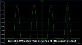
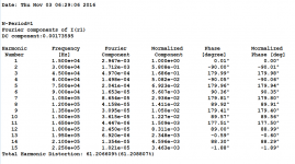
It eliminates crossover and thereby eliminates crossover distortion. It eliminates gm doubling in the output stage. It changes the supply current waveform from a half wave rectified sinusoid (with attendant high harmonics), into a full sinusoid riding atop a DC bias (with no extra harmonics).
Spectrum of "before" (without external current source) shown below, notice 58% 2nd harmonic at 30 kHz and 3% 7th harmonic at 105 kHz. How good is your power supply at 105 kHz? How good is your active circuitry's PSRR at 105 kHz?
_
Attachments
It changes the supply current waveform from a half wave rectified sinusoid (with attendant high harmonics), into a full sinusoid riding atop a DC bias (with no extra harmonics).
This one's the primary benefit as I see it. Then if you run a balanced config even the sinusoid left on the supply can be cancelled.
- Status
- Not open for further replies.
- Home
- General Interest
- Everything Else
- What is wrong with op-amps?