Hi
I made the recording asked by Hans yesterday.
Jacques
(See Post #54)
Jacques that is a lovely plot, confirming that 10 Hz is about the centre frequency of the worst subsonics.
Many thanks for the hard work.
Linsley-Hood wrote an article on "Active Filters" published in Electronics World issue of October 1991. One of the Low Pass variety used a combination of his bootstrap configuration and a paralled T section. If of any interest I can post a copy of the circuit.
I am familiar with the article.
It has to be said that whatever John's talents were, filter design was not one of them. Look closely at the response curves.
1) Surely the whole point about about vinyl is that it HASN'T changed over the last 40 years. (and it certainly hasn't improved)
2) No, it is pretty much standard practice for recording (meaning just mono below 150Hz)
3) About 20 dB below the audio with bad cart-arm combinations. I am concerned only with filtering out subsonic rubbish.
I am just wondering.
When the facts mentioned above are still being unchanged for more than 40 years, and proposals to filter out of phase "subsonic rubbish" going back as far as 1961, why has not one single commercial manufacturer of Phono Preamps ever made the logical step to implement this filter?
Or even more logical, why does not every (high end) commercial supplier of Phono Preamps have this feature.
Manufacturers are smart enough to implement features when it gives them a competitive edge.
I know there is a theory that this out of phase "rumble" could be what makes vinyl sound so good, but is there any proof for this?
Or could it be that not all LP's are produced with frequencies below 150Hz recorded in mono, that being the reason why it is not implemented in commercial products?
On the other hand, when out of phase rumble makes LP's sound so special, why filter a feature that makes it so special?
Read this as open questions. I do not have the answers, but there is something that just does not seem to be very logical.
Hans
I am familiar with the article.
It has to be said that whatever John's talents were, filter design was not one of them. Look closely at the response curves.
So is the response problem to do with the capacitor/resistor values and Q which could be changed or with the design concept to the point computer modelling would be a total waste of time? (Symmetrically or otherwise)
Last edited:
Hi
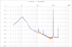
I did this morning the measurement of the 1 kHz track (left channel) with no antiskate.
Blue graph : original measurement already shown with antiskate (adjusted with tests record CBS laboratories)
Orange : same conditions except no antiskate.
Not significant change around 10-20 Hz.
But floor noise around 1 kHz lower (more for for f < 1 kHz). Force on the inner wall of the groove is higher when no anti-skate so noise floor on the left channel should be higher ?
Jacques
Attachments
Last edited:
I was thinking about my previous measurements and wondering why the floor noise is not the same both sides of the 1 kHz signal.
I did the measurments again with maximum attention at each step.
And I look at both channels.
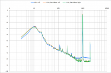
Blue graph : new measurement, left channel, anti-skate on; no change with former one
Orange : new measurement, left channel, anti-skate off
Green : new measurement, right channel, anti-skate off
Now, left and right are the same and have floor noise on both sides of the 1 kHz.
With no antiskate, the force of the sylus on the inner wall of the groove should be higher than on the outer wall when the disc is moving under the stylus, because of the geometry of the arm (offset angle ~26°, stylus overhang ~20 mm).
I did the measurments again with maximum attention at each step.
And I look at both channels.
Blue graph : new measurement, left channel, anti-skate on; no change with former one
Orange : new measurement, left channel, anti-skate off
Green : new measurement, right channel, anti-skate off
Now, left and right are the same and have floor noise on both sides of the 1 kHz.
With no antiskate, the force of the sylus on the inner wall of the groove should be higher than on the outer wall when the disc is moving under the stylus, because of the geometry of the arm (offset angle ~26°, stylus overhang ~20 mm).
Attachments
Hi Jacques,Hi
I did this morning the measurement of the 1 kHz track (left channel) with no antiskate.
Blue graph : original measurement already shown with antiskate (adjusted with tests record CBS laboratories)
Orange : same conditions except no antiskate.
Not significant change around 10-20 Hz.
But floor noise around 1 kHz lower (more for for f < 1 kHz). Force on the inner wall of the groove is higher when no anti-skate so noise floor on the left channel should be higher ?
Jacques
It's great that you could find the time to do this extra test.
It shows that the out of phase rumble noise can be manipulated, in this case by more than 2dB.
Of course one will need antiskating, so this is not the way to go. But by having induced more friction, you have added a bit of extra damping.
This seems to prove that for this type of rumble, even more arm/element damping is needed to reduce the rumble.
This is easier said than done, because how do you add damping to an existing set that doesn't provide this option?
In 1978 Shure introduced a 'viscous-damped Dynamic Stabilizer' attached to the V15 element, and maybe the Stanton 681 had something similar, but this idea has been abandoned.
The Citroen 2CV had shock absorbers that are fitted directly to the wheel suspension, with just one fixing point.
A mini version of that type of adjustable shock absorber should be available for fitting on the headshell.
Just because solving the problem at it's root is always better than symptom fighting.
Also because this rumble is causing IM distortion that no rumble filter can ever remove because the harm has already been done to the signal.
One last question to you Jacques, do you have woofers in your speakers that are visibly having trouble with the rumble and if yes, by how many dB should the rumble be attenuated to get it down to almost nil.
That would at least give an indication for a goal to be set for either a damping mechanism or a rumble filter.
Hans
Last edited:
I responded to your previous graph, but your last version seems to give cause for new questions.
Why does no antiskating give so much less noise around 1Khz ??
How is the sound reproduction? Jacques, do you hear any difference?
As Jan Didden already predicted, a dragon has many heads.
Hans
Why does no antiskating give so much less noise around 1Khz ??
How is the sound reproduction? Jacques, do you hear any difference?
As Jan Didden already predicted, a dragon has many heads.
Hans
Hi Hans and all
Sure my cart-arm needs damping but not easy to implement. I will think about that.
I have speakers but with no woofer. For the bass range they have 2x speakers ~ 6 inch diameter each. So the extreme bass range is limited to 40 Hz. They don't slowly move when I play a record.
And I am listening to music with earphones (Shure SRH940) most of the time.
So the resonance is not a big issue for me, I just try with your help to have a better understanding.
The only concern I would have is intermodulation of the audio signal by the 10-12 Hz parasistic signal. But I couldn't detect any intermodulation, except when I knock the turntable with my fingers.
Thank all for your comments, I am very happy to learn about these things with you.
Jacques
You mean with no anti-skating the noise floor is lower.
Jan
Yes and it surprises me
- why less noise
- and why on both channels ?
Jacques
Just curious. Even if cartridge and tonearm are properly compatible and matched for lower resonance; do compliance (Higher and lower) of cartridge have any significant effect on rumble noise ? I guess low compliance would give some damping so rumble noise would be less. Not sure though.
Regards.
Regards.
Yes and it surprises me
- why less noise
- and why on both channels ?
Jacques
If it is the same on both channels does that mean it is mainly a vertical component?
Jan
If it is the same on both channels does that mean it is mainly a vertical component?
Jan
Jan I think it is plinth coupled noise. The noise is coupled through the arm bearing structure. I had this on an old LP12/Itok arrangement.
If it is the same on both channels does that mean it is mainly a vertical component?
Jan
Vertical components are anti-phase.
It's impossible to see on my recordings (in the time domain) if the signals in the range 500- 2 kHz around 1 kHz are antiphase. But obviously there is an effect when turning anti-skating to 0 : the noise fllor reduced by 5-6 dB auround the frequency of the modulation.
But I can see that the parasistic signals on both channels at 10 -12 Hz are nearly perfect sine and are anti-phase (see my first post above), so coming from a vertical motion of the cart-arm, at its resonating frequency.
What we try to understand is how this nearly perfect sine is made. Groove and mechanical noises filtered by the high resonance ( nearly 20 dB peak, very poor damping) ?
Jacques
Here are the graphs taken from my pick up.
I noticed that the time signal from an unmodulated track, was not as what I saw before when using Adjust+.
The current measurements are made with my oscilloscope directly attached to the analog output signals.
The first image shows the time signals from both channels, with the sum of both in pink. They are clearly in antiphase.

Then the same recording, but now with the 12db/oct rumble filter switched on.

Next is the spectral information.Both channels from 0-150Hz with the rumble filter off, unmodulated track.

Then the same but now with the rumble filter on.

And the last picture shows the spectrum from 10Hz to 1Khz, no rumble filter and with a 1Khz test tone at 0dB.

Notice that when going from an unmodulated track to a 1Khz 0dB signal, the peak at 10Hz does not increase in amplitude.
However the noise further upwards in the spectrum is lower when playing the 1Khz tone compared to the unmodulated track, at 100Hz a difference of roughly 6 dB !
The 10Hz rumble lies ca 35dB below the 0dB 1Khz tone, almost 15dB better as Hyperman has recorded.
Hans
I noticed that the time signal from an unmodulated track, was not as what I saw before when using Adjust+.
The current measurements are made with my oscilloscope directly attached to the analog output signals.
The first image shows the time signals from both channels, with the sum of both in pink. They are clearly in antiphase.
Then the same recording, but now with the 12db/oct rumble filter switched on.
Next is the spectral information.Both channels from 0-150Hz with the rumble filter off, unmodulated track.
Then the same but now with the rumble filter on.
And the last picture shows the spectrum from 10Hz to 1Khz, no rumble filter and with a 1Khz test tone at 0dB.
Notice that when going from an unmodulated track to a 1Khz 0dB signal, the peak at 10Hz does not increase in amplitude.
However the noise further upwards in the spectrum is lower when playing the 1Khz tone compared to the unmodulated track, at 100Hz a difference of roughly 6 dB !
The 10Hz rumble lies ca 35dB below the 0dB 1Khz tone, almost 15dB better as Hyperman has recorded.
Hans
Hi Hans
So what we have in our both recordings is the same but unfortunately I have a very high resonance with the cartridge and arm.
My stylus is only 2 years old and I am listening to records 2 or 3 hours a week. So my stylus ran 250-300 hours. I consider it as still good.
The concern is the arm : no damping at all.
As said above, this resonance doesn't seem to give any intermodulation effect and when listening with my headphone everything seems to be OK.
With 1.5g vertical force I can track high level of modulation : +18 dB lateral, +12 dB vertical at 300Hz (test record CBS STR112)
I was very surprised the day I looked at the output signal in the time domain to discover such a 10Hz sinewave !
I also have to say that my PARIAA has a 0.2 dB loss at 20 Hz, so nearly no decrease in amplitude at 10 Hz.
What is the corner frequency of your rumble filter ?
jacques
Hi Hans
I also have to say that my PARIAA has a 0.2 dB loss at 20 Hz, so nearly no decrease in amplitude at 10 Hz.
What is the corner frequency of your rumble filter ?
jacques
My 12db/oct rumble filter has its -3dB point at 15Hz, at 10Hz it is ca. -8dB.
Without rumble filter my preamp has -0.1dB at 10Hz.
Hans
Again if anyone is interested there was a fifth order subsonic filter in Elektor issue of 7-8/96 that I can post. I have omitted the name in case someone has already seen this and is ready to belittle the author's design talents.
I have included a last image, showing IM distortion.
To make this visible in such detail, 32 frequency plots have been averaged with a filter bandwidth of 1 Hz.

What you see in the centre is again the 0dB 1Khz signal slightly polluted with IM products.
The most obvious ones are the +/- 50 Hz, at -72 dB below the main signal, picked up in some way from the 50 Hz mains.
The others, but more difficult to see, are sidebands at 9.5, 19 and 27,5 Hz at resp. -42 dB, -57 dB and -67 dB, all corresponding to the resonance frequency of my pick up arm.
So it is obvious that even with a rather well behaving arm, side bands are still taking their share. Extra damping could most likely help to reduce this IM distortion.
Hans
To make this visible in such detail, 32 frequency plots have been averaged with a filter bandwidth of 1 Hz.
What you see in the centre is again the 0dB 1Khz signal slightly polluted with IM products.
The most obvious ones are the +/- 50 Hz, at -72 dB below the main signal, picked up in some way from the 50 Hz mains.
The others, but more difficult to see, are sidebands at 9.5, 19 and 27,5 Hz at resp. -42 dB, -57 dB and -67 dB, all corresponding to the resonance frequency of my pick up arm.
So it is obvious that even with a rather well behaving arm, side bands are still taking their share. Extra damping could most likely help to reduce this IM distortion.
Hans
- Status
- Not open for further replies.
- Home
- Source & Line
- Analogue Source
- What is the ideal conventional rumble filter?- Douglas Self