Mr Self
I may have found a reason why the world is hesitating to integrate a “Devinyliser” like feature.
In your design you have assumed rumble with a perfect 180degrees out of phase.
For that you have perfectly constructed a Devinyliser.
I have simulated the 3rd order version presented in Linear Audio Vol 11, giving results below.

The green line represents the In Phase transfer and the Pink + Red ones the Out of Phase for both channels.
I have also included a grey line representing (In L + In R) but in this case of 180 degrees out of phase, the grey line is at minus infinity and therefore not visible in this figure.
However when recording a real life turntable signal from either an unmodulated track or a modulated track with 1Kh@0dB, the result from 10Hz to 100Hz when adding both channels would also have to be –infinity, like the grey line in the graph above.
This happens not to be the case. On average the damping is some -10 dB.
See figure below. Both channels are resp. represented in blue and red, and the mathematical sum of both in pink. All on the same scale.
At least 32 spectra have been averaged using a filter bandwidth of 1.5Hz. The used sample frequency was 200Khz, to prevent anything unwanted to fold back in the region of interest.

The reason for this lesser damping, can only be because of a phase difference. The L and R Channel are thus not perfectly 180 degrees out of phase.
In fact, looking at the figure, you will notice that around 300Hz both channels and their sum are equal in magnitude, telling that L and R are now 90degrees out of phase, and going further up in the scale, at 1KHz the Pink noise line lies 3dB above both channels, so L and R are now in phase.
There is thus a gliding scale in a changing phase from 1Khz downwards to 10Hz, going from almost zero to somewhat less than -180 degrees.
To see what happens with the Devinyliser, I have shifted the phase angle between both channels from 180 to 160 degrees. This produces the figure below.

Now the outputs of both channels with the devinyliser are no longer equal, but below 10Hz both channels converge to -15dB, just as the sum of both channels does represented in the grey line, the way my oscilloscope adds the two channels.
In fact this is a bit overoptimistic because instead of having a constant -160 degrees, there is a gliding scale going to -90 degrees at 300Hz.
With a gliding phase scale, the result will be like this:

Looking at the grey line, this looks quite similar to the damping that was realised with the scope recording.
Conclusion: This seems to be the maximum achievable damping of unwanted rumble with the Devinyliser.
In combination with a regular 2nd order Butterworth filter with -3dB at 14.5Hz, the transfer will look like the figure below, so at least a combination with a regular filter seems to be appropriate.

Hans
I may have found a reason why the world is hesitating to integrate a “Devinyliser” like feature.
In your design you have assumed rumble with a perfect 180degrees out of phase.
For that you have perfectly constructed a Devinyliser.
I have simulated the 3rd order version presented in Linear Audio Vol 11, giving results below.
The green line represents the In Phase transfer and the Pink + Red ones the Out of Phase for both channels.
I have also included a grey line representing (In L + In R) but in this case of 180 degrees out of phase, the grey line is at minus infinity and therefore not visible in this figure.
However when recording a real life turntable signal from either an unmodulated track or a modulated track with 1Kh@0dB, the result from 10Hz to 100Hz when adding both channels would also have to be –infinity, like the grey line in the graph above.
This happens not to be the case. On average the damping is some -10 dB.
See figure below. Both channels are resp. represented in blue and red, and the mathematical sum of both in pink. All on the same scale.
At least 32 spectra have been averaged using a filter bandwidth of 1.5Hz. The used sample frequency was 200Khz, to prevent anything unwanted to fold back in the region of interest.
The reason for this lesser damping, can only be because of a phase difference. The L and R Channel are thus not perfectly 180 degrees out of phase.
In fact, looking at the figure, you will notice that around 300Hz both channels and their sum are equal in magnitude, telling that L and R are now 90degrees out of phase, and going further up in the scale, at 1KHz the Pink noise line lies 3dB above both channels, so L and R are now in phase.
There is thus a gliding scale in a changing phase from 1Khz downwards to 10Hz, going from almost zero to somewhat less than -180 degrees.
To see what happens with the Devinyliser, I have shifted the phase angle between both channels from 180 to 160 degrees. This produces the figure below.
Now the outputs of both channels with the devinyliser are no longer equal, but below 10Hz both channels converge to -15dB, just as the sum of both channels does represented in the grey line, the way my oscilloscope adds the two channels.
In fact this is a bit overoptimistic because instead of having a constant -160 degrees, there is a gliding scale going to -90 degrees at 300Hz.
With a gliding phase scale, the result will be like this:
Looking at the grey line, this looks quite similar to the damping that was realised with the scope recording.
Conclusion: This seems to be the maximum achievable damping of unwanted rumble with the Devinyliser.
In combination with a regular 2nd order Butterworth filter with -3dB at 14.5Hz, the transfer will look like the figure below, so at least a combination with a regular filter seems to be appropriate.
Hans
Mr Self
I may have found a reason why the world is hesitating to integrate a “Devinyliser” like feature.
In your design you have assumed rumble with a perfect 180degrees out of phase.
Hello Hans
I am very glad that someone has put the Devinyliser to work in a real situation.
As you say, it is designed to remove signals that are purely vertical, and it's not to clear how else you could go about it. Your figure of 10 dB surprises me, though.
The reason for this lesser damping, can only be because of a phase difference. The L and R Channel are thus not perfectly 180 degrees out of phase.
In fact, looking at the figure, you will notice that around 300Hz both channels and their sum are equal in magnitude, telling that L and R are now 90degrees out of phase, and going further up in the scale, at 1KHz the Pink noise line lies 3dB above both channels, so L and R are now in phase.
There is thus a gliding scale in a changing phase from 1Khz downwards to 10Hz, going from almost zero to somewhat less than -180 degrees.
It is not obvious to me how vertical stylus movement can show this sort of differential phase shift. Do you have a hypothesis?
Last edited:
I am sorry, I have read dozens of papers, patents etc on the subject, but I cannot retrieve the two earlier proposals from 1961 and 1967, published before Macaulay, Langvad and Oldfield.
When I come across them I will let you know.
May be you are interested in the following list with over 150 references, all having to do with Record Players and their specific problems.
https://dl.dropboxusercontent.com/u/18462778/Pick-Up.docx
Thanks for that. I have been through the list of references, and while generally useful, sadly rumble filtering does not feature in it.
Concerning your other points, I am more a believer of "Less Is More", so I am in support of those manufacturers that have abandoned enabling too many options.
I see tone control and to a lesser degree balance adjust as Symptom Fighting.
Taking away the cause, if possible, is much better.
If everything is properly positioned, you probably won't need it.
Hans
Here I am afraid I have to disagree with you totally. If the symptom is a lack of bass, then I would turn up the bass control. It's cheaper than buying new speakers, which is what the hifi mags would tell you to do. You will have seen my approach to a decent tone-control in the Linear Audio preamp: http://www.diyaudio.com/forums/analog-line-level/280458-doug-self-preamp-linear-audio-5-a.html and it has bass and treble controls, each with variable frequencies. I think More is More here.
Likewise you might be able to do without a balance control if you had a totally symmetrical listening space and- significantly- perfectly matched loudspeakers, but how often is that the case?
Last edited:
(Elektor 5th-order filter, Post #117)Albeit for a home theater application.
That is not a filter configuration you see every day. I can report that it does exactly what it claims to do, giving a Butterworth response with a very useful 30dB/octave slope below about 15 Hz. I expect no less from Ton Giesberts, who I have worked with, and for whom I have much respect.
However...
10-off 2.2uF 1% capacitors are going to cost a fortune. I didn't find any in a half-hour search, but I can say a polyester 5% part is about a pound a go. Unfortunately with this configuration 5% is not going to be good enough if you want an accurate response. Using polypropylene to eliminate capacitor distortion will put the price up again, until those capacitors cost more than the rest of the equipment.
Were anyone to ask me, I'd design it as a 3rd-order plus 2nd-order (or maybe two 2nd-orders and a 1st-order if component sensitivity is really an issue) which would allow 5% caps to be used.
Most importantly, I'd scale the caps down to 220nF where polyprop becomes affordable.
If anyone is wondering, all those odd resistor values are in the E96 series.
Note the filter has a gain of +6dB, which isn't ideal for integrating into signal paths.
Last edited:
If we where all alike, life would be boring, wouldn't it?Here I am afraid I have to disagree with you totally. If the symptom is a lack of bass, then I would turn up the bass control. It's cheaper than buying new speakers, which is what the hifi mags would tell you to do. You will have seen my approach to a decent tone-control in the Linear Audio preamp: http://www.diyaudio.com/forums/analog-line-level/280458-doug-self-preamp-linear-audio-5-a.html and it has bass and treble controls, each with variable frequencies. I think More is More here.
Likewise you might be able to do without a balance control if you had a totally symmetrical listening space and- significantly- perfectly matched loudspeakers, but how often is that the case?
We are all aiming for different goals.
That's what can make discussions so interesting.
............. and never the twain shall meet!
Hans
Nothing. But I will. Can you give me the issue date?
Likewise, could you let me have the issue date of the Elektor filter?
It has set me thinking...
The latter is 7-8/96. All I have is a photocopy of the page not the actual issue. I had a lot of magazines and not the storage space - some of these had to go. I don't know if the reference T-Giesberts-964051 would help track this down.
I don't have the Williamson article dates - my source was a reprint booklet.
This can be seen online at http://audio.ring.lt/pp/williamson.pdf
It would have been a step to far in faith for me to have built something like this in transistors. If unusable I will know my caution was justified.
I was interested in the pix posted for a 2 pole subsonic filter. The results seem in line with my subjective impressions for one I built long ago.
(Elektor 5th-order filter, Post #117)
That is not a filter configuration you see every day. I can report that it does exactly what it claims to do, giving a Butterworth response with a very useful 30dB/octave slope below about 15 Hz. I expect no less from Ton Giesberts, who I have worked with, and for whom I have much respect.
However...
10-off 2.2uF 1% capacitors are going to cost a fortune. I didn't find any in a half-hour search, but I can say a polyester 5% part is about a pound a go. Unfortunately with this configuration 5% is not going to be good enough if you want an accurate response. Using polypropylene to eliminate capacitor distortion will put the price up again, until those capacitors cost more than the rest of the equipment.
Were anyone to ask me, I'd design it as a 3rd-order plus 2nd-order (or maybe two 2nd-orders and a 1st-order if component sensitivity is really an issue) which would allow 5% caps to be used.
Most importantly, I'd scale the caps down to 220nF where polyprop becomes affordable.
If anyone is wondering, all those odd resistor values are in the E96 series.
Note the filter has a gain of +6dB, which isn't ideal for integrating into signal paths.
I had the same thoughts about using 220nF caps - I had a stash of these in MKP at the time and was playing with active crossover systems - thinking about incorporating subwoofers.
Apart from the caveats you mention in my case there was that of the bulk of the equipment and all the leads to and from various pieces. The interests of domestic harmony prevailed over this.
I will keep watch for further developments
Last edited:
I don't have the Williamson article dates - my source was a reprint booklet.
This can be seen online at http://audio.ring.lt/pp/williamson.pdf
It would have been a step to far in faith for me to have built something like this in transistors. If unusable I will know my caution was justified.
I was interested in the pix posted for a 2 pole subsonic filter. The results seem in line with my subjective impressions for one I built long ago.
That's useful. I assume you're thinking of Figs 15 to 17? 30dB/oct, eh?
That's useful. I assume you're thinking of Figs 15 to 17? 30dB/oct, eh?
Right
Mr Self
I may have found a reason why the world is hesitating to integrate a “Devinyliser” like feature.
In your design you have assumed rumble with a perfect 180degrees out of phase.
For that you have perfectly constructed a Devinyliser.
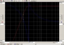
I have simulated the 3rd order version presented in Linear Audio Vol 11, giving results below.
View attachment 540971
The green line represents the In Phase transfer and the Pink + Red ones the Out of Phase for both channels.
I have also included a grey line representing (In L + In R) but in this case of 180 degrees out of phase, the grey line is at minus infinity and therefore not visible in this figure.
However when recording a real life turntable signal from either an unmodulated track or a modulated track with 1Kh@0dB, the result from 10Hz to 100Hz when adding both channels would also have to be –infinity, like the grey line in the graph above.
This happens not to be the case. On average the damping is some -10 dB.
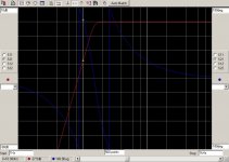
See figure below. Both channels are resp. represented in blue and red, and the mathematical sum of both in pink. All on the same scale.
At least 32 spectra have been averaged using a filter bandwidth of 1.5Hz. The used sample frequency was 200Khz, to prevent anything unwanted to fold back in the region of interest.
View attachment 540972
The reason for this lesser damping, can only be because of a phase difference. The L and R Channel are thus not perfectly 180 degrees out of phase.
In fact, looking at the figure, you will notice that around 300Hz both channels and their sum are equal in magnitude, telling that L and R are now 90degrees out of phase, and going further up in the scale, at 1KHz the Pink noise line lies 3dB above both channels, so L and R are now in phase.
There is thus a gliding scale in a changing phase from 1Khz downwards to 10Hz, going from almost zero to somewhat less than -180 degrees.
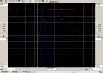
To see what happens with the Devinyliser, I have shifted the phase angle between both channels from 180 to 160 degrees. This produces the figure below.
View attachment 540973
Now the outputs of both channels with the devinyliser are no longer equal, but below 10Hz both channels converge to -15dB, just as the sum of both channels does represented in the grey line, the way my oscilloscope adds the two channels.
In fact this is a bit overoptimistic because instead of having a constant -160 degrees, there is a gliding scale going to -90 degrees at 300Hz.
With a gliding phase scale, the result will be like this:
View attachment 540974
Looking at the grey line, this looks quite similar to the damping that was realised with the scope recording.
Conclusion: This seems to be the maximum achievable damping of unwanted rumble with the Devinyliser.
In combination with a regular 2nd order Butterworth filter with -3dB at 14.5Hz, the transfer will look like the figure below, so at least a combination with a regular filter seems to be appropriate.
View attachment 540975
Hans
It might pay to measure the results on another turntable, cartridge, tonearm combination to see if there are any variations or things in common with yours.
Removing rumble is a waste of time. One should say analogue good or bad is what it is. Like film verses digital. It's almost like insisting people are slim to be beautifull. Mind you for 78's worth a try. 1938 Duke Elllington comes to mind. Rumble at a very high level at 20 Hz. The Alan Parker said to be stereo CD BBC records circa 1989 comes to mind. Parker would have been able to correct if as he was that type of engineer. Interesting he didn't. A real favorite of mine. Very interesting it need reallly good speaker to hear it. When you do it's not subtle. Will build one all the same as I have a big use on 78's. I presume it will work if a stereo PU with correct tip. I won't use it for LP's. None I own need it. Understand the reason to have, just don't see a need.
Off to do some work. Forgive English ect.
Off to do some work. Forgive English ect.
To me it would be like studio equalisers with spectrum analyser built in. One could even look at variable twin T in valve. Not easy to do. Simple so as to least colour the signal and only reject the actual problem, Leving sub bass alone, An ECC83 is a low distortion device. EF86 also and will offer feedback EQ at very low distotion. An FET opamp to follow inc RIAA.OPA2604 perhaps. A Sanyo bar graph LED driver after the filter could be OK. No real need to show exact frequency .Tape deck ones picked up rumble very well ( usually first two LED's ). Don't think a notch filter needed really as little is recorded that low. 20 dB change should be a big deal. That's like going from a - 48 dB 1950's cut to state of the art. If you filter your bass be aware midrange claity changes. This is how music works and a pipe organ shows this. It's the voice of the organ. The organ peddles can not often be heard until lets say until a tuba pipe played.The assisted tuba pipe will be louder and deeper when it's own power is unchanged. It forms a hetrodyne as our rumble will. As rumble was factored into cutting balance do not be surprised if something liked is now bass light. It is truely bass light as it no longer sounds like the master tape. Do not assume PU cartridge resonance a booster. The cutting will have factored it in. See bode plot below. The maths show the complexiity. Not really as there are rules that work to simple ratios. Keep to the rules and it should work first time.
http://fourier.eng.hmc.edu/e84/lectures/ActiveFilters/node4.html
http://fourier.eng.hmc.edu/e84/lectures/ActiveFilters/node4.html
Last edited:
To me it would be like studio equalisers with spectrum analyser built in. One could even look at variable twin T in valve. Not easy to do. Simple so as to least colour the signal and only reject the actual problem, Leving sub bass alone, An ECC83 is a low distortion device. EF86 also and will offer feedback EQ at very low distotion. An FET opamp to follow inc RIAA.OPA2604 perhaps. A Sanyo bar graph LED driver after the filter could be OK. No real need to show exact frequency .Tape deck ones picked up rumble very well ( usually first two LED's ). Don't think a notch filter needed really as little is recorded that low. 20 dB change should be a big deal. That's like going from a - 48 dB 1950's cut to state of the art. If you filter your bass be aware midrange claity changes. This is how music works and a pipe organ shows this. It's the voice of the organ. The organ peddles can not often be heard until lets say until a tuba pipe played.The assisted tuba pipe will be louder and deeper when it's own power is unchanged. It forms a hetrodyne as our rumble will. As rumble was factored into cutting balance do not be surprised if something liked is now bass light. It is truely bass light as it no longer sounds like the master tape. Do not assume PU cartridge resonance a booster. The cutting will have factored it in. See bode plot below. The maths show the complexiity. Not really as there are rules that work to simple ratios. Keep to the rules and it should work first time.
The Twin-T notch (band-stop) filter
I'm having real trouble trying to get any sense out of this.
Clutching at a recognisable concept, I will say that the twin-T circuit would be my last choice for a notch filter. More on that later.
Why would twin T not work ? In radio they did. Rumble usually is 23Hz + 100 Hz if a Garrard 401. In truth a rumble filter is a bit like curing the holes in cheese by killing the bacteria.The convetional filter as I said should worrk. Like Michael Gerzon who talked to me about filters. I favour passive twin T ( Michaels simplest solution I think ). Happy to be wrong. That why these pages exist. Even a bad I idea can cause the right debate. Michael proved the seemingly identical filter can sound different. Flutter echo I think was said. I might be mixing that with other things. KISS as is often said.
The twin-T is usually the last notch configuration you would use, because its notch depth depends critically on the matching of six components.
While we speak of notches:
Here is the simulated response of my 3rd-order elliptical filter. The notch is generated by a Bainter filter, which here gives a -65 dB with no adjustment or matching of parts. It is a truly beautiful circuit; the notch depth depends only on the opamp gain, which does not drift. The opamp models used were TL072, on the basis that whatever opamp was finally used it would have more gain than that.

Last night I built one, using 5532s. With no tweaking whatever the measured notch depth is greater than 95 dB. What about yer twin-T now, eh? The Bainter has another advantage in that it uses only two precision capacitors rather than three. It's also very good at making highpass notches, which is what you need for a highpass ellptical filter.
It is bitterly ironic that in this application a notch depth of more 50 dB is not really required.
You can see in the plot that there is massive attenuation at 10Hz, but compared with a 3rd-order Butterworth (red line) the -3dB point is higher and so the passband is less flat.
What is the answer? A 4th-order elliptical filter, perhaps. Building one now.
While we speak of notches:
Here is the simulated response of my 3rd-order elliptical filter. The notch is generated by a Bainter filter, which here gives a -65 dB with no adjustment or matching of parts. It is a truly beautiful circuit; the notch depth depends only on the opamp gain, which does not drift. The opamp models used were TL072, on the basis that whatever opamp was finally used it would have more gain than that.
Last night I built one, using 5532s. With no tweaking whatever the measured notch depth is greater than 95 dB. What about yer twin-T now, eh? The Bainter has another advantage in that it uses only two precision capacitors rather than three. It's also very good at making highpass notches, which is what you need for a highpass ellptical filter.
It is bitterly ironic that in this application a notch depth of more 50 dB is not really required.
You can see in the plot that there is massive attenuation at 10Hz, but compared with a 3rd-order Butterworth (red line) the -3dB point is higher and so the passband is less flat.
What is the answer? A 4th-order elliptical filter, perhaps. Building one now.
Last edited:
The only useful filter in this application is a matching filter based on the measured performance of tonearm/cartridge combination.
A narrow deep filter is pointless.
A narrow deep filter is pointless.
The only useful filter in this application is a matching filter based on the measured performance of tonearm/cartridge combination.
A narrow deep filter is pointless.
Would you care to share with us why you think so?
My understanding is that with a half-decent turntable almost all the subsonic rubbish comes from disc warps, usually amplified by the cartridge/arm resonance . (say 8 -12 Hz) I very much doubt if 100kg platters do any good at all.
yes disc warp and resonances cartridge arm. Some vintage LPs have rumble recorded.
Some turntables come with vacuum and are said to have less rumble.
But if one wants to "digitalize" these rare vintage LPs - some cost up to 3000 USD- why not lookk for a phone preamp that can handle up to 110mm/sec displacement , cracks, and resonance rumble and make the rumble etc. filter digital? That should be simpler and more effective. So you have an almost rumble/ crack free digital copy and never touch the original LP again( but sell it with a little profit?)
Why not use a higher order active HPF?
A 6th Order Sallen-Key 15Hz HPF with Butterworth response would be -21.6dB @ 10Hz and -.2dB @20Hz.
An 8th Order Sallen-Key 15Hz HPF with Butterworth response would be -27.5dB @ 10Hz and -.11dB @20Hz.
An 8th Order Sallen-Key 15Hz HPF with Elliptical response would be -53dB @ 10Hz and passband ripple of ±0.7dB from 20Hz to 100Hz.
The Red trace is amplitude response, the Blue trace is phase.
Attachments
- Status
- Not open for further replies.
- Home
- Source & Line
- Analogue Source
- What is the ideal conventional rumble filter?- Douglas Self