Hi
I also noticed the presence of a parasistic signal around 10-12 Hz at the output of my RIAA preamplifier.
I made some trials to try to find the origine.
I have a Thorens TD190 turn table with a Ortofon OMB40 MM cartridge.
I used a TASCAM HD-P2 to record the output in a .wav file I can analyse with Audacity.
I record the same LP (old LP from the seventies) at 2 different time ( 2 months ) but with the same equipment.
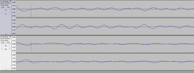
The I put the two files under the same window in Audacity, sliding the signal to have the same timeline ( unfortunately, the disk has some "clic" that make easy to find the time).
My observation in my system is that the parasistic signal is du to vertical modulation (identique but opposite in phase) but not the same at the same time so no reproductible as a signal cut in the disc.
In my situation, the 10-12 Hz parasistic signal is not in the LP.
Beside this the motor of the turn table produces rays at 21and 38 Hz, roughtly at -35 dB compare with a 0dB cut reference signal at 1 kHz
Jacques
I also noticed the presence of a parasistic signal around 10-12 Hz at the output of my RIAA preamplifier.
I made some trials to try to find the origine.
I have a Thorens TD190 turn table with a Ortofon OMB40 MM cartridge.
I used a TASCAM HD-P2 to record the output in a .wav file I can analyse with Audacity.
I record the same LP (old LP from the seventies) at 2 different time ( 2 months ) but with the same equipment.
The I put the two files under the same window in Audacity, sliding the signal to have the same timeline ( unfortunately, the disk has some "clic" that make easy to find the time).
My observation in my system is that the parasistic signal is du to vertical modulation (identique but opposite in phase) but not the same at the same time so no reproductible as a signal cut in the disc.
In my situation, the 10-12 Hz parasistic signal is not in the LP.
Beside this the motor of the turn table produces rays at 21and 38 Hz, roughtly at -35 dB compare with a 0dB cut reference signal at 1 kHz
Jacques
Attachments
Valid point, see below.The concave falloff probably arises from using a linear frequency scale, instead of logarithmic. Merely a presentational issue.

Notice that in the previous graph, the horizontal axis starts at ca. 1.1 Hz and not 0 Hz.
Hans
Can I float an idea? Others can shoot it down. What you are seeing is cartridge-arm resonance amplifying LF noise from groove roughness. Friction will pull the stylus forward, which the arm geometry will translate into a vertical motion. This is only a small effect, but amplified by the resonance. Someone (not me) may be able to estimate the size of this effect and see if it is plausible as a source of rumble.Hyperman75 said:I also noticed the presence of a parasistic signal around 10-12 Hz at the output of my RIAA preamplifier. . . . My observation in my system is that the parasistic signal is du to vertical modulation (identique but opposite in phase) but not the same at the same time so no reproductible as a signal cut in the disc.
@DF96
Thank you for your idea, that is what I was also suspecting...
The verticale resonance of my arm is around 10-12 Hz too.
The amplitude of this resonance is greater when tracking outer tracks than inner tracks on the disk.
I tried to change the resonance by adding little mass ( up to 5g) on the cartridge but I didn't notice change in the frequency of the parasistic signal.
I will try additional experiments to confirm your idea.
Apart from that I don't have any disturbing rumble (level much lower than groove noise).
Jacques
Can I float an idea? Others can shoot it down. What you are seeing is cartridge-arm resonance amplifying LF noise from groove roughness. Friction will pull the stylus forward, which the arm geometry will translate into a vertical motion. This is only a small effect, but amplified by the resonance. Someone (not me) may be able to estimate the size of this effect and see if it is plausible as a source of rumble.
I would expect friction to produce white noise over a restricted BW.
That is why I designed a second order high pass, Fo at 10Hz and a peak of 10db.
Feeding this simulated Arm/Element transfer curve with white noise with a BW of 100Hz, I got the following time signal.

This is not conforming to what Hyperman is showing us, so the "friction model" seems a bit unlikely to me.
Hans
Hyperman,
Could you make the same time recording with the element resting on the LP, with the drive belt removed and with the motor running.
That would exclude a number of possible causes.
Hans
Could you make the same time recording with the element resting on the LP, with the drive belt removed and with the motor running.
That would exclude a number of possible causes.
Hans
Would playing a blank record, with the anti-skate set so the tonearm doesn't move reveal anything useful?
If so, we could experiment using flat or warped, dirty or clean, 33 1/3 or much slower or much faster, etc...
You could even put a very small, light mirror (front reflection, not glass) on top of the cartridge, aim a laser at an angle onto it, and see the patterns on the wall, that would eliminate all electrical variables (cartridge output).
I owned a NAD 5120 turntable with a flat tonearm (oversimplified: a long and slim piece of PCB) and a good damper system (damping degree and damped frequency were adjustable). It came with a test record that alowed many adjustments incl. the determination of the tonearm resonance frequency. Tests showed that wet playback resulted in much lower resonance rumble (and less need for damping).Can I float an idea? Others can shoot it down. What you are seeing is cartridge-arm resonance amplifying LF noise from groove roughness. Friction will pull the stylus forward, which the arm geometry will translate into a vertical motion. This is only a small effect, but amplified by the resonance. Someone (not me) may be able to estimate the size of this effect and see if it is plausible as a source of rumble.
Mr. Self,
Do you have a copy of AudioXpress magazine, February 2011? An interesting article and warp filter circuit there from author Jeff Macauley.
Dave.
Do you have a copy of AudioXpress magazine, February 2011? An interesting article and warp filter circuit there from author Jeff Macauley.
Dave.
I owned a NAD 5120 turntable with a flat tonearm (oversimplified: a long and slim piece of PCB) and a good damper system (damping degree and damped frequency were adjustable). It came with a test record that alowed many adjustments incl. the determination of the tonearm resonance frequency. Tests showed that wet playback resulted in much lower resonance rumble (and less need for damping).
Hi franzm,
You mean this one I assume (see attached). It also has a 1KHz reference tone added to each low frequency test band, with both channels vertically modulated.
regards
Peter
Attachments
I did not take the RIAA curve into account while simulating the rumble.
Tomorrow I will add that, it will probably make some difference.
Hans
Tomorrow I will add that, it will probably make some difference.
Hans
Hi
I made the recording asked by Hans yesterday.
Thorens TD 192, Ortofon OMB40 cartridge
Vertical tracking force =1,5g, antiskating force adjusted with test record (CBS Laboratories, STR 112 bought in the seventies)
Recording system : TASCAM HD-P2, 24bits/192 kHz
Process : digital recording of the output of the PARIAA
Spectrum analysis with Audacity, data transfert to excel.
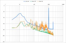
Blue graph : test record 1 kHz, at 0dB standard recording level; recording level in TASCAM ~ -7 dB
H2 -47 dB below H1
All others digital recordings with same level.
Green graph : stylus in the groove same LP, first track (outer), belt remove, motor OFF
Orange graph : stylus in the groove same LP, first track (outer), belt remove, motor ON
We ca see a lot of rays, some 10-15 dB above the groove noise in the range 60-800 Hz (blue gaph). I did the measurments 2 times, with great care.
Jacques
I made the recording asked by Hans yesterday.
Thorens TD 192, Ortofon OMB40 cartridge
Vertical tracking force =1,5g, antiskating force adjusted with test record (CBS Laboratories, STR 112 bought in the seventies)
Recording system : TASCAM HD-P2, 24bits/192 kHz
Process : digital recording of the output of the PARIAA
Spectrum analysis with Audacity, data transfert to excel.
Blue graph : test record 1 kHz, at 0dB standard recording level; recording level in TASCAM ~ -7 dB
H2 -47 dB below H1
All others digital recordings with same level.
Green graph : stylus in the groove same LP, first track (outer), belt remove, motor OFF
Orange graph : stylus in the groove same LP, first track (outer), belt remove, motor ON
We ca see a lot of rays, some 10-15 dB above the groove noise in the range 60-800 Hz (blue gaph). I did the measurments 2 times, with great care.
Jacques
Attachments
Very nice Jacques!
The motor 'rumble' is too high in frequency to be attacked by a traditional rumble filter I guess.
Jan
The motor 'rumble' is too high in frequency to be attacked by a traditional rumble filter I guess.
Jan
So the really low frequency stuff is not coming from the motor, but from the LP revolving.
Not sure, the motor stuff looks suspiciously like mains harmonics.
I have a friend who 'tunes' motors in the sense that he adjusts the phase shift cap for perfect 90deg phase shift. He checks this on a spectrum analyzer looking for harmonics and the 50Hz 'skirt' width. It really makes a big difference tuning the cap - on my Kuzma it needed about 10% more capacity and the spectrum really cleaned up a lot.
Edit misread you - you are right, the really low stuff seems to come from the rotation. Agreed.
Jan
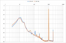
In addition I made a recording adding 6grams on top of the cartridge (then I re-adjust the tracking force to 1.5 g, of course).
blue graph : nominal as above
orange graph : same track with +6g on top of cartridege.
We can see a small decrease of the resonance frequency as expected, but the accuracy of the measurment is not good enough to be really sure.
If there is a real decrease in the frequency, this parasistic signal is not rumble produced by the turntable but groove noise amplified by the resonating tonearm-cartridge-stylus system.
In my system, rumble frequency components are 20 Hz and above.
Jacques
Attachments
In addition I made a recording adding 6grams on top of the cartridge (then I re-adjust the tracking force to 1.5 g, of course).
blue graph : nominal as above
orange graph : same track with +6g on top of cartridege.
We can see a small decrease of the resonance frequency as expected, but the accuracy of the measurment is not good enough to be really sure.
If there is a real decrease in the frequency, this parasistic signal is not rumble produced by the turntable but groove noise amplified by the resonating tonearm-cartridge-stylus system.
In my system, rumble frequency components are 20 Hz and above.
Jacques
Hallo Jacques,
Looking at the pictures that you have shared, I have attempted to make a model giving the same output in the frequency domain.

What I had to use to achieve this:
1) a second order high pass (your element) with res. freq. at 11 Hz and peak of 10dB.
2) A RIAA network behind this with a gain of -20dB @ 1Khz
3) A 4.2 Vrms sinus signal
4) A 225 mV rms White noise signal with a BW of 100Khz
5) A 180 mV rms white noise signal with a BW of 20Hz.
The sum of 3), 4) and 5) were fed to the input ( i.e. the element)
Result: The frequency plot conforms quite well to your plot.
Now without the sinus signal I have fed 4) and 5) to the input, which gave the following figure in the time domain.

Again the time plot corresponds relatively well to the figure that you have sent us.
So for some mysterious reason, there is a 20Hz Bandwidth white noise generator active when you are playing a record.
I have no idea what mechanism is causing this.
On the other hand, with the assumption that friction is producing only wideband noise, the time signal would look like this:

The green signal is the output from the element and blue is after RIAA correction.
And that blue signal happens to be more or less the signal that my record player is producing with an MC element with a 3x60 um stylus tip versus yours MM element with 5x70 tip when I am correct.
I will try do some more measurements on my record player in the coming days, when I can find the time.
To to conclude, what we have now is a model for your system, but no logical explanation for the 20Hz white noise being produced.
Hans
Hans
good job !
I think the question about the 20 Hz noise bandwith is still pending because when I look at my signal in the time domain, on a blank beetwen 2 tracks, I have a simple more or less sinewave around 10 hz as in your picture sel-frumble2.9 and not as in self-rumble2.2.
You can check that in my first post #41 yesterday.
Jacques
- Status
- Not open for further replies.
- Home
- Source & Line
- Analogue Source
- What is the ideal conventional rumble filter?- Douglas Self