My question is how the value of the resistor (R10) is calculated...
Missed this a few days back, ironically because I was at work on a delayed article for Jan Didden... on nested feedback - as well as more advanced schemes.
The primary issue with nested loops is stability, it's not intuitive.
One obvious answer to the OP's question is to simulate it, pick the value that provides acceptable stability.
This is most easily done in LT spice with a Tian probe.
A search of this forum will turn up examples to follow, I have posted a few tools that help to handle nested loops, they are in a thread by Paul (MCD99).
On the claims about the "sound" of nested loops, and similar.
Have any of these been done with the minimum requirements of competent tests? That is, blind and statistically valid?
Best wishes
David
Some of Valery's ideas are analysed in an article by Cherry and Cambrell in the 1982 April issue of JAES.
Anyone know of a PDF? I believe Cherry has made much of his work public domain.
Anyone know of other references, especially that include reverse transmission in the feedback loop?
Last edited:
Member
Joined 2009
Paid Member
Anyone know of a PDF? I believe Cherry has made much of his work public domain.
Jan knows where it is: http://www.diyaudio.com/forums/solid-state/40871-nested-feedback-loops.html
Jan knows where it is: http://www.diyaudio.com/forums/solid-state/40871-nested-feedback-loops.html
Thanks but that's only by Cherry, and I already have hardcopy.
I meant this one AES E-Library Output Resistance and Intermodulation Distortion of Feedback Amplifiers by Cherry and Cambrell.
The library has a paper copy but it's off site and not accessible til Monday.
Best wishes
David
I have done more work on nested loops with second order effects like reverse transmission thru the feedback network.
The maths is OK but I don't know how to interpret it yet, anyone have any references for this?
Last edited:
On a related note, I just got an email from AES today. It looks like access to the E-Library will now be included for members (yearly dues are going up about 20%, though). So those papers should be cheaper/easier to get, at least for members.
Cherry NDFL
Hi.
I found this article Cherry NDFL.
https://linearaudio.nl/sites/linearaudio.net/files/cherry ndfl.pdf
Regards
GE
Hi.
I found this article Cherry NDFL.
https://linearaudio.nl/sites/linearaudio.net/files/cherry ndfl.pdf
Regards
GE
Interestingly, I found that the simulations of Cherry's amp showed slightly worse distortion than Self's blameless, at lower frequencies but there was a reduction in crossover artefacts.
The higher distortion is almost certainly due to the increased degen which reduces the open loop gain compared with Self's, which would explain the differences. Cherry also made a point about taking the "miller" capacitor from the output terminal instead of the VAS to reduce crossover distortion. This works - see my suggested JLH update and the quasi version.
cheers
John
This was a basic design hence the relatively average linearity, otherwise such designs allow very low distorsion in the audio band, below 2uV distorsion for a 40V signal (at 1KHz), although as you point it the main advantage is drastically lower crossover distorsion, this allow to bias the OS at very low currents and still have ppm level distorsion.
I'm not sure where the question was put to me, perhaps here or not, but someone wanted to know if there were 5Kw mosfets available.
Yes, from MicroSemi. You can buy these from Digikey, but beware, they are around $US350 each. Not exactly cheap, but then, if you were driving a traincar they might be quite the ticket......
Microsemi Corporation APTM50UM09FAG-ND
MOSFET N-CH 500V 497A SP6 7 - Immediate
$353.53000 1 Bulk?
Active MOSFET N-Channel, Metal Oxide Standard 500V 497A 10 mOhm @ 248.5A, 10V 5V @ 30mA 1200nC @ 10V 63300pF @ 25V 5000W -40°C ~ 150°C (TJ) Chassis Mount SP6 SP6
Microsemi Corporation APTM100UM45DAG
MOSFET N-CH 1000V 215A SP6 13 - Immediate
$359.15000 1 Bulk?
POWER MOS 7® Active MOSFET N-Channel, Metal Oxide Standard 1000V (1kV) 215A 52 mOhm @ 107.5A, 10V 5V @ 30mA 1602nC @ 10V 42700pF @ 25V 5000W -40°C ~ 150°C (TJ) Chassis Mount SP6 SP6
Microsemi Corporation
MOSFET N-CH 1000V 215A SP6 10 - Immediate
$361.53000 1 Bulk?
POWER MOS Active MOSFET N-Channel, Metal Oxide Standard 1000V (1kV) 215A 52 mOhm @ 107.5A, 10V 5V @ 30mA 1602nC @ 10V 42700pF @ 25V 5000W -40°C ~ 150°C (TJ) Chassis Mount SP6 SP6
Microsemi Corporation APTM120UM70DAG
MOSFET N-CH 1200V 171A SP6 0
Standard Lead Time 22 Weeks
$343.79500 10 Bulk?
Active MOSFET N-Channel, Metal Oxide Standard 1200V (1.2kV) 171A 80 mOhm @ 85.5A, 10V 5V @ 30mA 1650nC @ 10V 43500pF @ 25V 5000W -40°C ~ 150°C (TJ) Chassis Mount SP6 SP6
They are out there - stay alert!!
Hugh
I found this article Cherry NDFL.
https://linearaudio.nl/sites/linearaudio.net/files/cherry ndfl.pdf
That is a simplified version.
The full slam is here > A new result in negative-feedback theory, and its application to audio power amplifiers - Cherry - 1978 - International Journal of Circuit Theory and Applications - Wiley Online Library.
But I still think it misses essential issues, I hope to discuss this with Dr Cherry soon.
Best wishes
David
I remember that at that time there was a NDFL-amp described in German magazine "ELRAD". These have been archived by Heise Verlag and are available there as a DVD.
Hi All,
I am building a mosfet o/p version of the JLH "Simple Class A" using IPP600N25N3s as o/p devices. I am planning to implement nested feedback so I read through the early pages of this thread a few months ago to get a better understanding.
My design currently has OLG of 100db and CLG of about 26db.
I will be experimenting and auditioning various versions to see which I prefer subjectely.
First I will try without nested FB - which is where I am now
Then will try with verying amounts of DC nested FB
Then will try with transitional nested FB with various values of R & C.
In earlier auditions I really liked the sound of DC nested FB with most of the OLG used by the FB from the driver stage and only 15-25db left for the o/p stage - the snag was that the bass seemed under damped - hence the motivation for using a transitional version.
Would be interested to hear others subjective preferences with different implementations of Nested Feedback
best wishes
mike
Last edited:
That is a simplified version.
The full slam is here > A new result in negative-feedback theory, and its application to audio power amplifiers - Cherry - 1978 - International Journal of Circuit Theory and Applications - Wiley Online Library.
But I still think it misses essential issues, I hope to discuss this with Dr Cherry soon.
Best wishes
David
Out of curiosity I built this Cherry NDFL in LTSpice because I didn't get the advantages for such a complicated feedback system over a simple second order feedback system only costing an additional resistor and a cap in series with the dominant cap.
So I made the traditional amp as in his fig. 2, with a gain of 21 and a BW of 300Khz.
Then going to Cherry's circuit I had to solve the following parameters:
BW = 300Khz = 1/tau x
taux = 3,33e-6
Beta = Rf1/(Rf1+Rf1) = 1/21
RC = Beta*taux = 0.16e-6
R = 100 thus C = 1.6 nF
Ry*Cy = taux
Ry = 2k thus Cy = 1.7 nF
taul = (sqrt3-1)*taux = 2.44e-6
Rl = 50 this output C = taux/Rl = 67nF
Cap parallel to Rf2 is taul/Rf2 = 122pF
I could not read the value of the output coil, so I made this one a 2 uH.
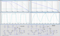
All these cap values seem rather over the top, and they are as seen in the FR below.
At the left the "traditional" amp. In the upper plot you see Open loop gain, resp closed loop gain.
In the plot below the step response.
At the right the Cherry amp with all the feedback caps and the extra gain stage.
Open and closed loop are much worse and so is the step response.
I played with all cap cap values, and did not manage to improve Open loop while keeping the BW of 300kHz.
Hans
Attachments
Your capacitance values are certainly high. The compensation capacitor C is dependent on the input degen. resistors. In Cherry's original he used 330 ohm, not 100, so I would expect to see a higher capcaitance than his original here (68p), but not 1.6nF
The 2nd stage was 470p not 1.7n. I'm not sure what you were aiming to achieve, here, because using only small signal transistors with a high bandwidth probably does not need Cheery's approach - in other words, unless you include power transistors of 2MHz you could make all the frequency components aim for a higher figure, I suspect.
I think that is it - your taux is too large by a factor 2 pi at least.
Last edited:
Hi Hans,
For more realistic R's and C's, please have a look at this (slightly modified) principal schematic and this amp.
Cheers,
E.
For more realistic R's and C's, please have a look at this (slightly modified) principal schematic and this amp.
Cheers,
E.
I would be more impressed if you had used the LTSpice file to prove your point.Your capacitance values are certainly high. The compensation capacitor C is dependent on the input degen. resistors. In Cherry's original he used 330 ohm, not 100, so I would expect to see a higher capcaitance than his original here (68p), but not 1.6nF
The 2nd stage was 470p not 1.7n. I'm not sure what you were aiming to achieve, here, because using only small signal transistors with a high bandwidth probably does not need Cheery's approach - in other words, unless you include power transistors of 2MHz you could make all the frequency components aim for a higher figure, I suspect.
I think that is it - your taux is too large by a factor 2 pi at least.
The amplifier at the left works fine, and Cherry suggests to have created an open loop gain that goes much farther in frequency and then starts to go down with resp. 18, 12 and at last with 6dB/oct.
Nothing of that kind is visible here.
Conclusion can only be that either his formulas or the circuit diagram are wrong.
Hans
Well, I don't use LT spice as I use another simulator. I don't know what point you are trying to make as I merely pointed out that your calculation of taux shoud have been 1/(2.pi.BW). That seemed to me to be why your capacitances seemed to be larger which is what I thought your concern was. I wasn't criticising your circuit as such other than to question why using only small signal transistors. I did not say it did not work!
And, Cherry's NDFL circuit was only a 2 stage which means only a 12dB/octave highest slope.
And, Cherry's NDFL circuit was only a 2 stage which means only a 12dB/octave highest slope.
Last edited:
I think that is it - your taux is too large by a factor 2 pi at least.
You were absolutely right about the taux.
Cherry was using radians.
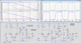
So I changed all the caps, now being 6.28 times smaller.
I also changed the output transistors in Darlingtons, to cause less load on the stage driving them.
But as expected, it did not change anything to the fact that the open loop gain is still going down with 6dB/oct instead of the resp 18, 12dB/oct.
Only the BW has been shifted a factor 6.28.
See image below, showing both open loop and closed loop FR, where both versions now have the same -3dB closed loop BW of 300Khz.
Still no advantage whatsoever over the simple version.
Hans
Attachments
Last edited:
How are you calculating open loop gain? The second capacitor (C) is a "hidden" compensation (the one directly from the output rail to the base of the VAS) which needs to be "open circuited" to obtain the OLG, which probably causes you to see a 6dB/octave. Cherry showed a Bode plot without any feedback effects then adding one of the three at at time. I'm sure you will see the 12dB slope if you start from scratch.
Well, I don't use LT spice as I use another simulator. I don't know what point you are trying to make as I merely pointed out that your calculation of taux shoud have been 1/(2.pi.BW). That seemed to me to be why your capacitances seemed to be larger which is what I thought your concern was. I wasn't criticising your circuit as such other than to question why using only small signal transistors. I did not say it did not work!
And, Cherry's NDFL circuit was only a 2 stage which means only a 12dB/octave highest slope.
I find the supplied graph rather confusing.
I looks as if the Gain without feedback is 18dB/oct, changing into 12dB/oct at 1/taux
To get a stable amp, this means that the closed loop gain should intersect this with 6dB oct, which is obviously the function of the cap parallel to Rf2.
Maybe one should read the full article nr11 in the reference list, but I don't have that.
IMO something seems absolutely incorrect in this article.
Hans
Attachments
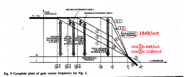
That set of Bode plots referred to an illustrative (outline) circuit of at least 3 nested feedbacks. Which implies at least three separate gain stages, (giving 18dB/octave) that's all really. His NDFL design which was popularised in ETI (1983) used only 2.
If you haven't read the original articles it is well worth doing so, if you can track them down. I think the IEEE had one under the circuits group and possibly the AES published one- not sure now.
If you haven't read the original articles it is well worth doing so, if you can track them down. I think the IEEE had one under the circuits group and possibly the AES published one- not sure now.
Last edited:
That set of Bode plots referred to an illustrative (outline) circuit of at least 3 nested feedbacks. Which implies at least three separate gain stages, (giving 18dB/octave) that's all really. His NDFL design which was popularised in ETI (1983) used only 2.
If you haven't read the original articles it is well worth doing so, if you can track them down. I think the IEEE had one under the circuits group and possibly the AES published one- not sure now.
I'll try to dig deeper into this article, however his comment that:
"once the demanded gain 1/beta and the critical frequency 1/taux are chosen, the circuit almost designs itself".
is not exactly what I experienced.
Hans
- Home
- Amplifiers
- Solid State
- What is nested feedback, how it realy works and some examples...