ANyone have schematic or example?
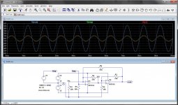
In the thumbnail is a simple example using a couple of op-amps. Each has their own local feedback resistor (R1, R2). R6 is feedback from the output of the second stage to the input of the first. So, nested feedback.
Each stage has a gain of about 4 so total gain == 16
Add R6 to give feedback from the output to the first stage now gain == 5
Attachments
Last edited:
I believe the gain is 1+R6÷R3=1+47÷10=5.7 and most of that gain is generated in the second stage. 4.3.
Last edited:
Yes, that's how it works.
Heaven forbid I should round off a little in conversation...
Yes .. ~16 without R6, ~5.7 with it.
Heaven forbid I should round off a little in conversation...
Yes .. ~16 without R6, ~5.7 with it.
Last edited:
Douglas- nice explanation.
I should have said that the feedback capacitor C between the output rail and VAS base was one of the nested feedback paths!
The point being that all feedback paths need to be disconnected to see the open loop gain.
I should have said that the feedback capacitor C between the output rail and VAS base was one of the nested feedback paths!
The point being that all feedback paths need to be disconnected to see the open loop gain.
Nesting should of course not be a target in itself, but it has to serve a purpose.
Cherry's purpose after all was to get a reduction in distortion.
I was concentrating on an increased open loop gain, to give a higher feedback ratio through an increased loop gain.
But Cherry constructed something from several locally fedback parts, that overall gave a misleading unspectacular 6dB/oct open loop gain roll off.
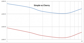
But when measuring distortion, the true benefits became clear, see image below showing 3rd harmonic from 1 to 10 Volt @ 1kHz, just as in the supplied article.
Against the simple version without nesting, Cherry's version reduced the distortion by a factor 100.
Hans
Cherry's purpose after all was to get a reduction in distortion.
I was concentrating on an increased open loop gain, to give a higher feedback ratio through an increased loop gain.
But Cherry constructed something from several locally fedback parts, that overall gave a misleading unspectacular 6dB/oct open loop gain roll off.
But when measuring distortion, the true benefits became clear, see image below showing 3rd harmonic from 1 to 10 Volt @ 1kHz, just as in the supplied article.
Against the simple version without nesting, Cherry's version reduced the distortion by a factor 100.
Hans
Attachments
As Cherry showed, then, Hans.
But you still seem to have trouble with the 6dB/octave?
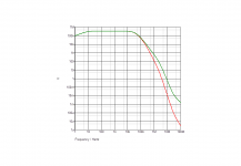
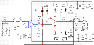
If I remove all the frequency controlling components (the input filter, both "C" capacitors and "Cy" the OLG falls at a rate of around 18 db/octave.
The two curves in the image are with and without the output inductor.
But you still seem to have trouble with the 6dB/octave?
If I remove all the frequency controlling components (the input filter, both "C" capacitors and "Cy" the OLG falls at a rate of around 18 db/octave.
The two curves in the image are with and without the output inductor.
Attachments
As Cherry showed, then, Hans.
But you still seem to have trouble with the 6dB/octave?
If I remove all the frequency controlling components (the input filter, both "C" capacitors and "Cy" the OLG falls at a rate of around 18 dB/octave.
The two curves in the image are with and without the output inductor.
No, I have no problem whatsoever with a 6dB slope, but as I explained, reading the article I was almost pushed in another direction of thinking.
And also the text, choose your critical Frequency 1/taux caused me to make the 2Pi mistake.
About the open loop shape, this depends largely on the components used.
As an example I have added the OL response of my circuit drawn in red, after having removed all caps.
On top of that I have projected in blue a second order FR, showing that up to 400kHz, response is 6dB/oct. From thereon it continues with 18dB/oct.
In teal you can see the open loop of the "simple" circuit, showing that from 1Khz and upwards, the Cherry version has 50dB or more open loop gain.
So when distributed over several nested subsystems, a theoretical distortion reduction of 50dB can be achieved, but phase distortion reduces this in this case to an excellent 40dB.
So at the end after some frustration, everything was alright and it was a fruitful exercise.
In this sort of complex cases, it's always good to see a complete example being worked out with FR images to prevent misunderstandings.
But they are probably in his reference #11.
And thanks for making me aware of the 2Pi misunderstanding.
Hans
Attachments

Last edited:
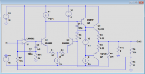
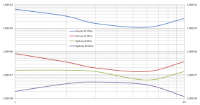
Still looking into nested solutions, I constructed this version with a single LM4562 Op Amp around the "simple" version as shown before.
The advantage of this design is that it can be applied to any existing amplifier without modification.
As a second function it will keep the Main Amp's output voltage at the same level as the OpAmps input level, removing the need for large Caps in the feedback path of the Main Amp.
As can be seen, the simple amp with this nested OpAmp design performs significantly better as the more complex Cherry design when both loaded with 25R.
Even when loading this version with 8R beats the Cherry loaded with 25R at arms length.
Hans
P.S. the distortion graph shows the 3rd harmonic while applying a 1khz signal from 1 to 10 Volt.
Attachments
Last edited:
I used the .step command to step through the amplitude.
Using .four, LTspice showed all the distortions at those various steps.
Then I entered these values in Excel in a scatter plot for the 4 different versions and there you are.
Hans
Using .four, LTspice showed all the distortions at those various steps.
Then I entered these values in Excel in a scatter plot for the 4 different versions and there you are.
Hans
The discrete node must be converted to an inverting inclusion.I used the .step command to step through the amplitude.
Using .four, LTspice showed all the distortions at those various steps.
Then I entered these values in Excel in a scatter plot for the 4 different versions and there you are.
Hans
Actually that is a reason why I like more transparent equipment. It's up to the mastering engineer how he wants the music to sound. I don't feel the urge to second-guess him and/or to modify his work.
Imagine an art lover taking a brush to the Mona Lisa because he likes his colors 'warmer' 😎
Jan
My sentiments exactly, during production use whatever distortions you want, at home give me no distortion.
I prefer a leery smirk.......
Every amplifier distorts. The ear is far more sensitive to higher harmonics, and even at tiny levels, it detects it subliminally spoiling the sense of 'natural' sound.
Some of the very low THD amps do this too.
Like anything, idealogies beat reality every time.
Every amplifier distorts. The ear is far more sensitive to higher harmonics, and even at tiny levels, it detects it subliminally spoiling the sense of 'natural' sound.
Some of the very low THD amps do this too.
Like anything, idealogies beat reality every time.
I think TPC (which I use a lot) and TMC ( which I used on my e-Amp) work very well at using the available loop gain to reduce distortion to low levels. It seems to me that nested feedback requires a lot of engineering effort for moderate improvements. TPC and TMC will get you a c. 14 dB or more improvement at 20 kHz for the cost of a resistor and a small good quality cap.
That said, there is a lot to be gained by just following the basic rules as set out by Self and Cordell in getting unwanted distortion to negligible levels before lowering it further with feedback.
That said, there is a lot to be gained by just following the basic rules as set out by Self and Cordell in getting unwanted distortion to negligible levels before lowering it further with feedback.
Last edited:
I think TPC (which I use a lot) and TMC ( which I used on my e-Amp) work very well at using the available loop gain to reduce distortion to low levels. It seems to me that nested feedback requires a lot of engineering effort for moderate improvements. TPC and TMC will get you a c. 14 dB or more improvement at 20 kHz for the cost of a resistor and a small good quality cap.
That said, there is a lot to be gained by just following the basic rules as set out by Self and Cordell in getting unwanted distortion to negligible levels before lowering it further with feedback.
You also can try OITPC (Output Inclusive TPC). 🙂 I use it now in all my power amps.
OITPC - Output inclusive TPC (not TMC)
Hi Andrew,
You are right that TPC is simple by only having to add a resistor and a cap, giving reasonable reduction in THD, see here:
Simulating single pole vs. Transistional Miller Compensation (TMC)
But saying that Nested Feedback requires a lot of engineering effort for moderate results is far besides truth.
Results are not moderate at all and engineering effort means adding an opamp two resistors and a cap, or in TPC an additional cap and resistor see here some results.
What is nested feedback, how it realy works and some examples...
The challenge may be the power supply for the opamp, but this all peanuts compared to building a main amp.
But the biggest objection I have against TPC is that not only distortion goes down, but also the musical sensation of the sound becoming a bit harsh.
This is purely subjective, but after all I'm the only one listening to my gear, so for me it matters.
When trying to investigate what could be the reason, I found that settling time becomes much larger with TPC, but whether this can be the reason, I really don't know.
It would be nice if others could try to listen to both versions, single pole and TPC and hear their experience.
But as you mention, when following basic rules, distortion can be negligible without any need for TPC.
Hans
Last edited:
You also can try OITPC (Output Inclusive TPC). 🙂 I use it now in all my power amps.
OITPC - Output inclusive TPC (not TMC)
Interesting additions to TPC.
What about settling time compared to simple TPC ?
Hans
- Home
- Amplifiers
- Solid State
- What is nested feedback, how it realy works and some examples...