Well, my smart phone is in bits still, but that's the last thing I attempted to repair. I really need to find my Maggylamp ...
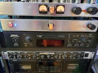
More of a rebuild than a repair, but the hum in the DAC is now gone, and I now have another bluetooth for guests and 5 extra inputs. The only thing I'm missing is an LED to tell you if you have selected optical or coax 🙂
Attachments
Hi kodabmx,
What is that tube unit on top?
I have the same Nixie tubes (Russian) in my clock (Russian). I don't like the "2", being an upside down "5".
-Chris
What is that tube unit on top?
I have the same Nixie tubes (Russian) in my clock (Russian). I don't like the "2", being an upside down "5".
-Chris
It's the front of my integrated amp. 🙂
I know what you mean about the upside down five. I've ordered up a couple of IN-8 tubes for my next IA build.
I know what you mean about the upside down five. I've ordered up a couple of IN-8 tubes for my next IA build.
You fix cameras?
You are a brave man!
-Chris
yeah started 8mm, Hi8, mini DV, DVD than digital still camera... 1st one of those was Sony Mavica than DSC-P1 still do Sony ALPHAS out of warranty
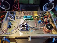
A model railway shuttle controller.
Symptoms were it powered up with LED on for 4 seconds.
Then relay clicked, it crashed and restarted again.
It got stuck in this loop.
A quick inspection of the pcb spotted a flywheel diode not soldered on one leg.
Soldered it and everything was fine.
Symptoms were it powered up with LED on for 4 seconds.
Then relay clicked, it crashed and restarted again.
It got stuck in this loop.
A quick inspection of the pcb spotted a flywheel diode not soldered on one leg.
Soldered it and everything was fine.
A Pioneer SX-1280 that was serviced very poorly elsewhere. Man, it was rough. Incorrect transistors soldered on the cut legs of the original ones. Really tacky (sic).
Why Pioneer used solid core wire I'll never know. Thin too! So replaced all the wire in that channel with colour 18 gauge stranded wire. It blew the outputs (yikes!).
Now it's fine.
-Chris
Why Pioneer used solid core wire I'll never know. Thin too! So replaced all the wire in that channel with colour 18 gauge stranded wire. It blew the outputs (yikes!).
Now it's fine.
-Chris
I don’t repair much, just break stuff...
It's types like YOU that have helped keep me in business for so long.
LOL!
A Pioneer SX-1280 that was serviced very poorly elsewhere. Man, it was rough. Incorrect transistors soldered on the cut legs of the original ones. Really tacky (sic).
Why Pioneer used solid core wire I'll never know. Thin too! So replaced all the wire in that channel with colour 18 gauge stranded wire. It blew the outputs (yikes!).
Now it's fine.
-Chris
Doncha just LOVE those jobs, Chris?
LOL!
I've had my share, trust me. 😉
Maybe because stranded wire is ANNOYING to work with? I absolutely HATE using stranded in a chassis.
That may be true, and stranded wire isn't my favorite, but it would have helped if they used heavier wire for starters, and the wire is used in places that flex when serviced. All the connections were failing and were about a #22! I'm surprised it got enough current through there to short the output transistors. They used two runs of #20 from the power supply capacitors.
What Pioneer really needed was a connector between the driver PCB and heat sink mounted parts. That, or use stranded wire (but wire wrap tools don't take stranded wire). Really, a #20 wire or #18 for solid would have been more appropriate.
Basically, it is a cheaply made set sold for a lot of money. After putting it together it developed a new problem. A regular, fast loud clicking sound from both amplifier modules. The previous guy was into the power regulator board too. Bloody hell, back in I go. Tapping that PCB makes both amplifiers crackle (pulled the links to the preamplifier). Oh fun, oh joy, oh bliss.
-Chris
I see what you mean. 22 in an SS amp is a little thin for power! Gremlins from bad repairs are always fun to chase...
I use 22 for almost all my chassis wiring, but it's tube stuff so HV, low current. 18 for power tube heaters though. All Solid.
The only time I buy stranded is by mistake lol
I use 22 for almost all my chassis wiring, but it's tube stuff so HV, low current. 18 for power tube heaters though. All Solid.
The only time I buy stranded is by mistake lol
Had a Nakamichi Dragon Tape , Auto Azimuth run out of Limits sometimes with audible toc toc toc and some intermittent issues in Sound.
First complete orange cap Changing Game, the azimuth Problem was the Right Pinch Roller did not move upwards.
Pretty much work for disassemling and remove the whole Roller Assy.
This thingy had to be released by a Friend with special Tools to avoid damage, since part is obsolet.
All fine again after 2 days of work.
The Dragon is a complicated machine. I was authorized warranty and worked on a few over the years. I wish I still had my jigs and tapes (they went with the shop when I sold it).
-Chris
-Chris
Many of the old Fisher solid state receivers from the late 60's used push on connectors for each board so that the boards could be removed for service. The connectors and the pins they fit on were tin plated. These got the green growth in the south Florida humidity which resulted in the common "frying egg" sound, or intermittent popping or channel death. Once the growth was bad enough to cause a customer complaint it has breached the plating resulting in severe corrosion on the connector. The "official" Fisher cure was to simply solder the connectors to the board.
I don't remember for sure, but I think they used solid core wire too.
I don't remember for sure, but I think they used solid core wire too.
- Home
- Member Areas
- The Lounge
- What did you last repair?