OK, I'm working on a list of parts to order to make the Whammy a preamp with two inputs. Was able to find suitable parts and part numbers by doing searches on this forum. The list is almost done but it's time to pick a few op amps for experimentation.
There are many versions of the same op amps. For example, if you look up OPA2134 on a site like Mouser it'll return 8 versions. 6 are obviously surface mount but that still leaves 2 that have legs: opa2134pa and opa2134pag4.
I've gone through some of the specifications but I'm no electronics guru and it's bewildering. Is there a way to tell what makes these two different - or does it even matter?
This isn't the only op amp I'd like to try and the others have the same issue. Do a search and many variants show up in the search. Are there any rules for choosing the right op amps for the Whammy?
Or does someone have a list of op amps and their Mouser/Digikey order numbers?
Many thanks for any insight.
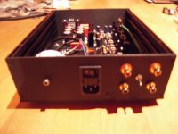
Is this safe to run without an enclosure for a while? I don't want to use it without one if there's an electrocution risk.
Hey guys,
Curiosity got the better of me about a month ago and I ordered one of these ebay HDAM fully discrete dual op amps from China which are based on Marantz HDAM circuit model.
It finally turned up today with delivery to the UK taking about four weeks.
Only had a brief listen so far (little one is not very happy with chicken pox) but first impressions are good which hopefully bodes well as the Burson V6 op amps took a while to burn in before they started sing so am thinking these might be similar.
https://www.ebay.co.uk/itm/Full-Dis...e=STRK:MEBIDX:IT&_trksid=p2060353.m1438.l2649
Photo not uploading for some reason will try again later
Pic of orientation in link below if needed I had to search a bit for a pin out diagram.
PASS DIY Headphone Amp - WHAMMY | Page 8 | Headphone Reviews and Discussion - Head-Fi.org
Last edited:
The WHAMMY has lured me to this forum.
I'm investigating this build and have put together this BOM. Feel free to copy it but please let me know if you have any feedback before I pull out the credit card.
web - Octopart
Also, there doesn't seem to be a bypass for an amp here. this seems like an oversight. is there a reason for this or is there a simple way to add one. I think it would be a bit annoying having to fiddle with cables everytime i switch between headphones and loudspeakers.
Cheers,
tom
answer to MASHMAN
Hello Tom,
you can add an switch and the RCA / chinch-outputs for an amp pretty
easily. Output + (left and right) from Whammy - PCB to switch / from the switch to headphone output or to the RCA output. So you need a 2-pole-selectorswitch. You also could run the headphone-output and the RCAs parallel.
Was discussed in this Whammy-thread. Have to check which post#.
Greets
Dirk
Check Photos in post #877 for connecting RCA / headphonejack in parallel
(no switch).
Greets Dirk
(no switch).
Greets Dirk
opa2134pa and opa2134pag4.
I've gone through some of the specifications but I'm no electronics guru and it's bewildering. Is there a way to tell what makes these two different - or does it even matter?
If you look at the packaging info section of the datasheet,
both OPA2134PA and OPA2134PAG4 orderable parts give devices
marked OPA2134PA.
The "G4" indicates a low halogen lead free process:
http://www.ti.com/support-quality/environmental-info/lead-free/lead-free-conversion.html
Note the OPA2134PA is also lead free.
So beyond a possible difference in the lead free process, I don't
expect a difference between the two.
Dennis
Check Photos in post #877 for connecting RCA / headphonejack in parallel
(no switch).
Greets Dirk
Aha, thanks. that's a nice build. i guess the pre-amp idea is great. only that i don't thing my current amp will play nice with that and i'll need to go find a class a power amp to build and then i'll be lost in aiyAudio forever!😉
answer to MASHMAN
Yes! Lost in the audio-universe!
This is what happened to me several times in my life.
Addiction to motorcycles and audio.....
I thought I was cured. But it came back many times 😀
Cheers
Dirk
Yes! Lost in the audio-universe!
This is what happened to me several times in my life.
Addiction to motorcycles and audio.....
I thought I was cured. But it came back many times 😀
Cheers
Dirk
The WHAMMY has lured me to this forum.
I'm investigating this build and have put together this BOM. Feel free to copy it but please let me know if you have any feedback before I pull out the credit card.
web - Octopart
Also, there doesn't seem to be a bypass for an amp here. this seems like an oversight. is there a reason for this or is there a simple way to add one. I think it would be a bit annoying having to fiddle with cables everytime i switch between headphones and loudspeakers.
Cheers,
tom
Could you not use a pair of rca outs with a sorting TRS jack (I think that's the right terminology) which disconnects the rca output when phones are plugged in?
Could you not use a pair of rca outs with a sorting TRS jack (I think that's the right terminology) which disconnects the rca output when phones are plugged in?
Yes. Place resistors of 27-50ohm (whatever you have in your box) in series with those RCA's output.
Last edited:
The WHAMMY has lured me to this forum.
I'm investigating this build and have put together this BOM. Feel free to copy it but please let me know if you have any feedback before I pull out the credit card.
Some of the order lines have either no stock or minimum quantities of 4,000 (or 10,000... 🙂 ) but the parts look to be good stuff.
Also, there doesn't seem to be a bypass for an amp here. this seems like an oversight. is there a reason for this or is there a simple way to add one. I think it would be a bit annoying having to fiddle with cables every time i switch between headphones and loudspeakers.
Absolutely an oversight, and will be remedied with the chassis kit when that becomes available. A switching jack can be used and an output set or RCAs installed on the panel. Place some resistance in series with the outputs, 27-50 ohm or so. A "build-out" resistor.
NMJ6HF-S Neutrik | Mouser
An externally hosted image should be here but it was not working when we last tested it.
Finally finished my build after weeks.
But I have no audio coming from the left channel.
What are some things to check for? I have tried swapping up the op amp from a AD8397 to a OPA1612.
With the OPA1612, there is no right channel audio, and the left channel seems to give an output but still pretty quiet.
But I have no audio coming from the left channel.
What are some things to check for? I have tried swapping up the op amp from a AD8397 to a OPA1612.
With the OPA1612, there is no right channel audio, and the left channel seems to give an output but still pretty quiet.
An externally hosted image should be here but it was not working when we last tested it.
An externally hosted image should be here but it was not working when we last tested it.
An externally hosted image should be here but it was not working when we last tested it.
An externally hosted image should be here but it was not working when we last tested it.
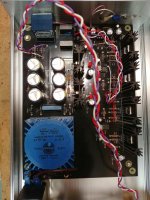
You will get crosstalk when the input wires of both channels a braided together.
I replaced the braided input wiring with a shielded wire, separate for each channel. each shield is attached to (the common) ground on the RCA side and at the attachment to the board.
before using this wire, I tested it for leakage. I connected one end to the signal generator (square wave, ~8.3KHz, ~1.5Vpp), shorting the other end with a 100kohm resistor. like I did with the unshieled wire supplied with the kit, I wrapped around the shielded one another, bare wire and connected to the other scope channel. unlike the kit wire, this one leaked no signal to the wrapped wire.
this also reduced the crosstalk between one input to the other from 30mv pp to about 10.
I still see imperfect leading edge on the output for the above input square wave.
any further ideas are more than welcomed,
Shmulik
But I have no audio coming from the left channel.
What are some things to check for? I have tried swapping up the op amp from a AD8397 to a OPA1612.
With the OPA1612, there is no right channel audio, and the left channel seems to give an output but still pretty quiet.
Does this mean it plays fine with the AD8397?
Some of the order lines have either no stock or minimum quantities of 4,000 (or 10,000... 🙂 ) but the parts look to be good stuff.
Good for quantity discount...and for building more amps. 🙂
Absolutely an oversight, and will be remedied with the chassis kit when that becomes available.
That will be nice. I'm liking more and more the idea of a preamp with
headphone out (or is it a headphone amp with preamp out? 🙂 )
Dennis
- Home
- Amplifiers
- Pass Labs
- "WHAMMY" Pass DIY headphone amp guide