Thanks for all the help guys! love the amp so far. Slight hiss with sensitive stuff but definitely wasn't designed for this. Works great for my HE6SE though.


I learn a lot from these troubleshooting threads so can you clarify a little? When you say backwards does that mean you had u2 and u3 swapped?I installed the regulators backwards... I (painstakingly) swapped them around and now it works!
I learn a lot from these troubleshooting threads so can you clarify a little? When you say backwards does that mean you had u2 and u3 swapped?
I had U2 and U3 swapped. When I flipped them everything worked as normal. So if anyone has an issue where you get no output when the amp is on but very distorted output when it's turned off, that might be the reason.
Question about building a Whammy without a volume pot. I built myself an Academy Audio BIB + VCX module in a Galaxy Chassis with 3 XLR inputs and two RCA outputs to use as a preamp. One output feeds my ANK EL34 tube amp and I would like the other to feed the Whammy and use the unit to adjust volume.
Can I just use resistors ranging from 10k to 50k here? Is the below correct?

Can I just use resistors ranging from 10k to 50k here? Is the below correct?
- resistor from pad 1 to 2
- jumper pads 2 and 3 together
- Do the exact same for pins 4,5,6 (other channel)
Or, should I wire my input rcas directly into the output of the pot and bypass the 2.2K resistors and C1/C5?
You are supposed to assemble and test the power supply alone first. Only then proceed to building the headphone amp section.View attachment 1249245
I had U2 and U3 swapped. When I flipped them everything worked as normal. So if anyone has an issue where you get no output when the amp is on but very distorted output when it's turned off, that might be the reason.
Last edited by a moderator:

One correction made as requested by member adason, to the previous post. It was the addition of the letter P.
One correction also made since I was there, I thought the word assemble deserved the addition of the letter M.
I trust I have done well.
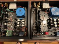
It almost took me a year before I could find the time to finish my WHAMMY build after ordering the PCB.
But recently I had a whole day I could spend on making the housing for it, here's some pics of the end result.
Now I can't wait to buy a suitable headphone to listen with, with what I have (a very basic Grado) it's allready pretty allright.
.jpeg")
.jpeg")


.jpeg")
.jpeg")


But recently I had a whole day I could spend on making the housing for it, here's some pics of the end result.
Now I can't wait to buy a suitable headphone to listen with, with what I have (a very basic Grado) it's allready pretty allright.
Attachments

Thanks! I'm happy with the result also.
A few moths ago I have had a listening session at Headphone auditions, and after that decided I am going to buy a Hifiman HE1000, Listened to quit a few but this one was by far the best value for the money. Unfortunately I can't find any reviews in combination with the WHAMMY, But I suppose it must be good, Maybe I just go there again and bring my Whammy to try.
A few moths ago I have had a listening session at Headphone auditions, and after that decided I am going to buy a Hifiman HE1000, Listened to quit a few but this one was by far the best value for the money. Unfortunately I can't find any reviews in combination with the WHAMMY, But I suppose it must be good, Maybe I just go there again and bring my Whammy to try.
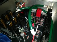
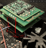
The Burson V6 Vivid was provided unsolicited by John Garcia of Burson who wanted my to post pictures of their opamp in my builds. Both units are using Sparkos voltage regulators and one of them are using the Sparkos Pro opamp. The Burson appear to have tighter bass, but the Sparkos a more opened midrange. The Sparkos require about an hour to stabilize for DC offset adjustments. Since they are stacked, it took me a few days to get the Sparkos adjusted. The Sparkos are also sensitive to variations in ambient temps. DC offset in the Burson are not possible, but the opamp appear to be more stable in terms of DC offset.
Attachments

Fantastic build, @Avalfa 🙂
What's the model of your potentiometer?
@RYC2000 , I also see more DC offset out of the Sparkos Vs Burson, but I did not fiddle with resistors around the Op Amp.
Have you checked for oscillations?
I have not tested the pro version, but I have not managed to get a fully stable SS3602, despite multiple decoupling trials:
Sparkos SS3602 (Left) Vs Burson V6 vivid (Right)

The interesting part is that the Vivid actually has a faster rise & fall time, and the SS3602 oscillation has the same pattern regardless of the level.
So I'm thinking that the only thing that might help stabilize SS3602 here is adding the feedback capacitors C2/C7 to limit bandwidth ?
THD+N was lower on the SS3602 (harmonics in the ~-115dB range @8Vrms ; ~100dB @2Vrms IIRC), compared to the V6 vivid and classic, (~-80dB range @8Vrms ; ~95dB @2Vrms). - For context, all my listening is done with <1Vrms.
Subjectively, the SS3602 are worse: flat sound stage, lack of dynamics, especially in low frequencies, sterile and cold sound, odd decay/reverb, constantly trying to highlights details which sounds like compression to me. Quiet parts in the music are boosted, my friend described this as hearing "constant pressure".
V6 Classic and Vivid are my favorites, those days I stick to the Classic as the Vivid can be a bit more hot in the treble at times in comparison.
The difference between the two is very audible, but both sound fantastic and have their pros and cons. (I use a Topping A30pro/D30pro stack for direct relative comparison).
I hear that Burson might be releasing their V7 version soon, I'd be very interested to try it.😉
What's the model of your potentiometer?
@RYC2000 , I also see more DC offset out of the Sparkos Vs Burson, but I did not fiddle with resistors around the Op Amp.
Have you checked for oscillations?
I have not tested the pro version, but I have not managed to get a fully stable SS3602, despite multiple decoupling trials:
Sparkos SS3602 (Left) Vs Burson V6 vivid (Right)
The interesting part is that the Vivid actually has a faster rise & fall time, and the SS3602 oscillation has the same pattern regardless of the level.
So I'm thinking that the only thing that might help stabilize SS3602 here is adding the feedback capacitors C2/C7 to limit bandwidth ?
THD+N was lower on the SS3602 (harmonics in the ~-115dB range @8Vrms ; ~100dB @2Vrms IIRC), compared to the V6 vivid and classic, (~-80dB range @8Vrms ; ~95dB @2Vrms). - For context, all my listening is done with <1Vrms.
Subjectively, the SS3602 are worse: flat sound stage, lack of dynamics, especially in low frequencies, sterile and cold sound, odd decay/reverb, constantly trying to highlights details which sounds like compression to me. Quiet parts in the music are boosted, my friend described this as hearing "constant pressure".
V6 Classic and Vivid are my favorites, those days I stick to the Classic as the Vivid can be a bit more hot in the treble at times in comparison.
The difference between the two is very audible, but both sound fantastic and have their pros and cons. (I use a Topping A30pro/D30pro stack for direct relative comparison).
I hear that Burson might be releasing their V7 version soon, I'd be very interested to try it.😉
Last edited:
Thanks Martigane,
The potentiometer is one (unbranded,Chinese?) I ordered from audio phonics in France. 10k value and the mechanism is a bit stiff, if you get me right. That's what the reviews mentioned, and indeed is the case.
Therefore I ordered a few different knobs to try, and with the one I mounted (solid CNC made aluminium) which has some weight/mass that's no problem at all, and it's quite a nice potentiometer for the price, (somewhere around €25-30 if I remember right.)
The only thing I miss so far after a week use, is a power LED in the front, to see if it's on or off.
First I decided on purpose not to place one to keep the front clear, design wise.
Now I am making plans/ thinking of a solution with a glass fibre and an LED somewhere inside.
And make a 1 mm hole in the front somewhere. Or something like that. Not Shure yet what it will be.
For a few songs I tried it with a basic BB opa 2134 which I had laying around, after the first power on, top be sure I wouldn't toast the Burson opamp. When all seemed fine, I put in the Burson (vivid I think it was I ordered). My first thought was different sound with the BB. However
I liked the Burson, and was wondering how much burn-in time would it take for the Burson to be at its finest?
10k value might be too low, depending on your source. I read that typically 20k minimum is advised. I had a hard time finding big enough knobs.
Since you use the LED psu configuration, it'd be smart to use optic fiber and reuse that free light indeed.
I can't really comment on burn in of Op Amps as I was too busy swapping them around.
I think it has minimal impact here.
Since you use the LED psu configuration, it'd be smart to use optic fiber and reuse that free light indeed.
I can't really comment on burn in of Op Amps as I was too busy swapping them around.
I think it has minimal impact here.
The Burson V6 Vivid was provided unsolicited by John Garcia of Burson who wanted my to post pictures of their opamp in my builds. Both units are using Sparkos voltage regulators and one of them are using the Sparkos Pro opamp. The Burson appear to have tighter bass, but the Sparkos a more opened midrange. The Sparkos require about an hour to stabilize for DC offset adjustments. Since they are stacked, it took me a few days to get the Sparkos adjusted. The Sparkos are also sensitive to variations in ambient temps. DC offset in the Burson are not possible, but the opamp appear to be more stable in terms of DC offset.
Have a look at this:
The IC on the photo is one of those exotic OPAmps.
For good decoupling results, the L should be as short as possible and W should be as wide (thick) as possible.
Now, consider this:
L is probably 20-30 mm (!!!), and W is negligible.
Any effort to decouple that "OPAmp" would be annulled by a very long L and narrow W. Completely useless at high frequencies.
A completely different layout is required, if those exotic IC / OPAmps are to be used, to allow them OPAmps to be soldered much closer to the ground fill (and Vcc/Vee, whose length & thickness are as important as the ground wire/trace length & thickness)
With WHAMMY, use a JFET OPAmp with a low input bias current. Once happy with the sound, remove the IC socket and solder the OPAmp straight to the PCB.
The Vcc/Vee decoupling electrolytes do not have to be 220uF... even 22uF will be more than enough (and much preferable, actually, if a uniform very low voltage rail impedance is desirable at the broad frequency spectrum range). Actually, a 10uF is all that is needed.... but I'd definitely try 4.7uF as well.
Attachments
Yes, I think Mooly or someone earlier shown in this thread how to best decouple, I do the same and solder directly the cap on the OpAmp, with shortest leads possible.
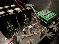
I am currently evaluating the impact of the amplifier temperature on the sound.
This is somewhat related to @sp33ls questions in #4,321
Config:
There seems to be a temperature sweet spot striking an optimal compromise, to my ears at least.
I've done this test 1 year ago, and again last week, with the same observations.
I can check where the amp is at by measuring the voltage across the 5.1Ohms R37 PSU resistor.
In all cases, I verified that the circuit was 100% stable (scope), but did not have a chance to hook Audio Precision at the different temperatures.
The sweet spot could be further improved if I could recover the bass depth and dynamic of the "too cold" config.
Interesting thing is that the sweet spot position also seems to be the one that keeps closer temperature between P/N output devices.
This is likely a coincidence, since in my view there's no guarantee that the P & N curves would best match at the same temperature.
-> Is it advised try to keep all output devices at the same temperature? Any expert care to comment on that?
Interesting to see that the circuit self-stabilises and draws less current as temperature increases. No run-away there.
I have 2 extra Whammy PCBs and will likely build a new one using FQP3P20/FQP3N30 (if I ever can order them) and a big heatsink on the side, rather than a balanced version which sound like too much work.
-> Is there a maximum recommended output bias, assuming heat sinking / PSU is adequate?
Looking at the datasheet, I'd say no, as I'd run into thermal issues well below 500mA anyway.
I am currently evaluating the impact of the amplifier temperature on the sound.
This is somewhat related to @sp33ls questions in #4,321
Config:
- Output transistors IRF9610PBF & IRF610PBF at 82mA output Bias (6.9Ohms output resistor)
- 22V trafo
- LED PSU config +/-16.6V
- Burson V6 Classic (it sees +/- 15.3V)
- Heat sink thermal resistance improved ~+50% compared to stock
- C2/7 feedback cap not used.
There seems to be a temperature sweet spot striking an optimal compromise, to my ears at least.
I've done this test 1 year ago, and again last week, with the same observations.
I can check where the amp is at by measuring the voltage across the 5.1Ohms R37 PSU resistor.
In all cases, I verified that the circuit was 100% stable (scope), but did not have a chance to hook Audio Precision at the different temperatures.
| Voltage across R37 | Output transistor heatsink temperature | Listening impressions | |
| Too cold (lid open) | 1.003 | ~40C (feels slightly warm) | Dry, analytical, more defined and dynamic. Wider Sound stage, but not realistic/coherent. Bass is deep and dynamic but does not have much body/fat/warmth. Cymbals have a too bright sheen that even seems to resonate during the decays, with worse color gradient. (like the "one note bass", but in the highs) |
| Sweet spot (lid half way) | 0.999 | ~50C (warm, no pain) | Sound stage seems to click in, and imaging becomes very precise, tangible, and "holographic". Ideal balance between the above and below extremes. |
| Too warm ( lid & vent closed) | 0.993 | ~60C (can hold 5s before pain) | Wet, softer transients, narrower sound stage with limited depth, erased spatial clues, with less contoured imaging. Cymbals sound too dark, more lush. More euphonic. |
The sweet spot could be further improved if I could recover the bass depth and dynamic of the "too cold" config.
Interesting thing is that the sweet spot position also seems to be the one that keeps closer temperature between P/N output devices.
This is likely a coincidence, since in my view there's no guarantee that the P & N curves would best match at the same temperature.
-> Is it advised try to keep all output devices at the same temperature? Any expert care to comment on that?
Interesting to see that the circuit self-stabilises and draws less current as temperature increases. No run-away there.
I have 2 extra Whammy PCBs and will likely build a new one using FQP3P20/FQP3N30 (if I ever can order them) and a big heatsink on the side, rather than a balanced version which sound like too much work.
-> Is there a maximum recommended output bias, assuming heat sinking / PSU is adequate?
Looking at the datasheet, I'd say no, as I'd run into thermal issues well below 500mA anyway.
Last edited:
@Martigane Sorry for the late reply. I have been busy looking at other things on diyaudio and only realized that I got reply to my post today. I have not checked for oscillations. I only got my scope recently and still learning how to use it. I had a really high DC offset with the SS3602 and went with the SS2590 solely because I can adjust it. Even so, it was a pain to get the offset in both channels to be in the single digit mv. You have to wait until the temperature is stabilized, and one being on top of the other does not help. You can only adjust one at a time, and the operating temp of that lower one is different as you remove the opamp on top. It is also affected by ambient temperature of your room. If your room is cool, the DC offset goes more negative and go more positive if your room is warmer. I did not listen to the Whammy with the SS3602.
I did not look for sound staging during this evaluation. The HD6xx were not known for sound staging. I only listened tonal changes and noticed the Sparkos have a more open and full midrange compared to the Burson Vivid. I have the SS2590 in a Geshelli J2S DAC playing to my stereo and noticed no problems with imaging. Unfortunately, the Burson would not fit inside the Geshelli DAC for a comparison.
I did not look for sound staging during this evaluation. The HD6xx were not known for sound staging. I only listened tonal changes and noticed the Sparkos have a more open and full midrange compared to the Burson Vivid. I have the SS2590 in a Geshelli J2S DAC playing to my stereo and noticed no problems with imaging. Unfortunately, the Burson would not fit inside the Geshelli DAC for a comparison.
@Extreme_Boky Thank you for your tips. I will have to see how I can rearrange the parts on the board so I don't have to use the extenders.
Looking for some help, finished my Whammy initial testing of power supply right on, 18V, Stuffed board, everything check twice and wired, now VDC between R10mand R30 9v as is R13and R14, unit has no sound and R37 and R20 smoke and get very hot, rechecked all connections, no solder bridges around regulators, diodes correct polarity. Any thoughts? I see someone else had same issue but I couldn't find resolution
- Home
- Amplifiers
- Pass Labs
- "WHAMMY" Pass DIY headphone amp guide