That is a very classy build, everything very well thought of! Thanks for sharing and congrats!!!
Rafa.
Rafa.
That is a beautiful build. Congratulations.
Hello Jeremy,
excellent build quality and a nice 'woody' design!
Enjoy the sound!
Cheers
Dirk 😀


That is a very classy build, everything very well thought of! Thanks for sharing and congrats!!!
Rafa.
Thanks! Yes I am happy with how it turned out, sounds great!
Now to decide whether it is worth getting those OPA627s 😀
!!!Help please!!!
Hello there,
this is Daniele from Italy.
I'm building a Whammy but I have some problem.
I was ok on PSU testing with voltmeter Regulator configuration option 1 - "LED reference" and I moved on but at the end I can't hear any sound to right channel just left one and volume is very low also with Alps potentiometer at full course.
I'm using Talema 70065K transformer with 220 VAC power input.
Also Nichicon and Elma condensers along with OPA627AP amp.
I also add Vishay 4N35 with dot on notch side on PCB and mosfets are FQP3P20 on Q2 and Q4 and FQP3N30 on Q1 and Q3.
R9, R10, R13, R14, C2 and C7 are empty.
Do you have any idea or suggestion in order to check what was incorrect please?
I'm not so expert so please give me some step by step suggestions if possible and above all thank you very much in advance for your time and your support.
Have a great day!
https://i.postimg.cc/63kXhX20/IMG-9198.jpg
Without reference to my own, are the capacitors and diodes in the correct orientation next to the PSU regulators?
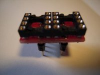
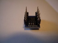
There are many adapters available:
- 2- single - opamps to dual - opamp
- SOIC8 to DIP8
and many more...
The problem is often the space around the opamp socket on the WHAMMY-pcb.
The caps byside the opamp will have to be bent away.
Sparkos Labs, Inc. SOIC to DIP adapter for surface mount applications
Single-to-Dual Op Amp Adapter - BrownDog Adapters - 021001
and many more....
Greets
Dirk 😀
!!!Help please!!!...
The OPA627AP has only a single amplifier in it. The Whammy needs a dual amp chip.
Just to compound on this answer, in case there is need: the opamp implementation on this Whammy requires a dual op-amp that amplifies both channels. You have a single op-amp, so you have a full channel silent, as you have already figured out.
You just need to put in place a very basic dual opamp to check that all works, and then you can start swapping / rolling opamps.
I would suggest to try the LM833... something very basic! Then put on the more expensive parts.
Rafa.
to RobLK
Hello RobLK,
sure you need two OPA627 (one for each channel) on a single-opamp-to-dual-opamp-adapter.
I did this. It is possible.
Greets
Dirk
Hello RobLK,
sure you need two OPA627 (one for each channel) on a single-opamp-to-dual-opamp-adapter.
I did this. It is possible.
Greets
Dirk

to RobLK
You can also implement two SOIC8-single opamps to a DIP8-dualopamp-socket.
One single opamp is on top of the mini-pcb, the other 'downside' or under deck.😉
Cheers
Dirk
You can also implement two SOIC8-single opamps to a DIP8-dualopamp-socket.
One single opamp is on top of the mini-pcb, the other 'downside' or under deck.😉
Cheers
Dirk
Attachments

I forgot these very nice adapters:
Sjostrom Audio - ADP01 ADP02 ADP03 ADP04 High End SMD to DIL adapters
Cheers
Dirk 😀
Sjostrom Audio - ADP01 ADP02 ADP03 ADP04 High End SMD to DIL adapters
Cheers
Dirk 😀
Just to compound on this answer, in case there is need: the opamp implementation on this Whammy requires a dual op-amp that amplifies both channels. You have a single op-amp, so you have a full channel silent, as you have already figured out.
You just need to put in place a very basic dual opamp to check that all works, and then you can start swapping / rolling opamps.
I would suggest to try the LM833... something very basic! Then put on the more expensive parts.
Rafa.
Thank you all.
I will take suggestion from Rafa and I will start with a very basic OP Amp in order to verify if everything is ok. Then I think I’ll move to Burson V6 Classic Dual because it seams to have interesting characters I’m searching for.
I’ll keep you posted as soon as I’ll have parts...
Thanks a lot again!
Good choice.
At first I did not like much the V6 classic as it is less dynamic than the V6 vivid and has less bass slam, more bass bloom, but it is also less strident in high frequencies (which makes it sound less bright / darker overall) and has sweet delicate mids. A less analytical and more enjoyable experience in the end.
Good luck, have fun!
There are many adapters available:
Yes, many good choices, some have even designed their own op amp. I see Dannybarry has found another choise.
Just to compound on this answer, in case there is need: the opamp implementation on this Whammy requires a dual op-amp that amplifies both channels. You have a single op-amp, so you have a full channel silent, as you have already figured out.
You just need to put in place a very basic dual opamp to check that all works, and then you can start swapping / rolling opamps.
I would suggest to try the LM833... something very basic! Then put on the more expensive parts.
Rafa.
Hello again,
unfortunately I just put the LM833N inside the Whammy and the problem is the same if not worst.
No audio at all, well I can hear some very distorted audio signal only if I turn whammy on and when off power switch, I can hear that very ugly and distorted sound like if capacitor are loosing their power (or charge) and at the end (few seconds of distorted audio) no sound again when full off.
The only things I did differently from the original BOM is to use Nichicon Muse capacitor 220UF / 25V instead of 50V but also Mr Colburn told in his very firsts posts to feel free to use 25V version without disadvantages.
C13 and C23 are WIMA 0,1 100-
C20 is .22UF 275 VAC instead of 250, part number R46KN322000M1M from the original BOM list but as I told on my first post PSU test was right, BTW 275VAC on C20 could be a problem?
Capacitor and diodes are added with right polarity, already double checked.
I'm actually in very deep water and I don't know what check (and how) in order to solve this problem.
Any idea to some of you Masters, please?
Thanks again in advance!
Best,
DannyBarry
Have you actually measured any DC voltages on the board to see if that shows a problem?
If you have an LM833 fitted then measure and record the voltage on every pin and post the results here.
If you have an LM833 fitted then measure and record the voltage on every pin and post the results here.
Thank you Mooly.
I'm a very newbie, I build some PCB but this is my first real project and I don't know how to measure, but I can try to do it...
I placed black probe on earth and red on every pin of the LN833 inserted, power on the unit.
NOTCH HERE (ON THE CENTER)
PIN1 -3,50 ______ PIN8 -2,05
PIN2 -6,27_______ PIN7 -3,35
PIN3 -0,2________PIN6 -5,53
PIN4 -17,91______ PIN5 -0
Thanks to internet search PIN4 (V-) to PIN7 (V+) reads 15,03V
Really hope this is the right procedure. Thanks a lot again!
Last edited:
So that seems to show a positive supply issue. Pin 8 should be positive 15 or 18 volts depending on your supply voltage. There should 30 to 36 volts between pins 4 and 8 depending on your exact supply voltages.
So check the 47 ohm marked R35 on the diagram at the start of the thread and also confirm (do this first) that the positive supply going into the resistor (it should be present on at least one end of the resistor) is in fact correct.
If that is missing then you need to look at the power supply.
So check the 47 ohm marked R35 on the diagram at the start of the thread and also confirm (do this first) that the positive supply going into the resistor (it should be present on at least one end of the resistor) is in fact correct.
If that is missing then you need to look at the power supply.
- Home
- Amplifiers
- Pass Labs
- "WHAMMY" Pass DIY headphone amp guide