I heard from Pete. There have been some tragedies in the lives of those close to him. Keep him in prayer. I'm sure he will be back soon.
Blessings, Terry
This is still4given's POST 282 from 22 DECEMBER 2013
That there is a fair total sum involved for those who have not received their boards yet is obvious. For some the money involved is a reasonably large sum, and I can well understand the hunger for information. But I do find this searching obits a tad goulish. It is quite clear from still4givens post quoted above that Pete has had a personal family tragedy. That, I believe, is adequate information. still4given has had contact, hence the quote above, and has since then sensibily kept out of it.
I know that for some it leaves a sour taste, but I would strongly resist the temptation to speculate on line regarding this matter.
Last edited:
This is still4given's POST 282 from 22 DECEMBER 2013
That there is a fair total sum involved for those who have not received their boards yet is obvious. For some the money involved is a reasonably large sum, and I can well understand the hunger for information. But I do find this searching obits a tad goulish. It is quite clear from still4givens post quoted above that Pete has had a personal family tragedy. That, I believe, is adequate information. still4given has had contact, hence the quote above, and has since then sensibily kept out of it.
I know that for some it leaves a sour taste, but I would strongly resist the temptation to speculate on line regarding this matter.
well said Dear Brianco.
TO-3 Suggestions
Terry... what TO-3 devices are you using. I'm considering a 40vdc +/- supply with the VSSA and I already have the 4 position TO-3 heatsinks.?
Thanks, Bill
I've been playig my TO-3 VSSA on 4 ohm and 37V rails for a few days now without any issue that I can see. What should I be looking for to know if there is a problem?
Thanks, Terry
Terry... what TO-3 devices are you using. I'm considering a 40vdc +/- supply with the VSSA and I already have the 4 position TO-3 heatsinks.?
Thanks, Bill
Finally! My VSSA Fet ccs came to life...😀
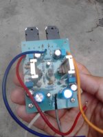
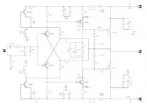
I have incorporated PMIs schematic revision to Shaans moded pcb design done by me...🙂 2SK246GR for the ccs and the ultrahigh-definition 2SA1406/SC3600 (typical 400mhz) with 47pf comp caps for VAS. I have omitted the 10uf bypass caps (very expensive in my place 🙁) and back to 47ohms for the current source resistor (tied to input diff emitters) as in LCs original because my ccs fets are GR types they only generate about 2.6-6.5ma. I have tested the amp for 2hours of playtime and the main heatsink barely got warm. Everything sounds brilliant! Tiny circuit with a huge soundstage! 😎
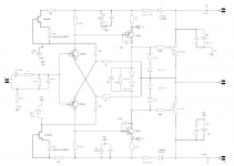
I am being tempted to lower the 47pf to 22pf but don't really know what would be the outcome. Some questions...touching the VAS heatsink produces a slight hum,is this normal? Are they supposed to be grounded? I have attached my revised schematic (taken from PMIs original) please do not hesitate to post your comments/observations as I am no engineer. I am only relying on my trusted DMM. 🙂
P.S. I just hope PMI won't find my posting to be intrusive.
Cheers!
I have incorporated PMIs schematic revision to Shaans moded pcb design done by me...🙂 2SK246GR for the ccs and the ultrahigh-definition 2SA1406/SC3600 (typical 400mhz) with 47pf comp caps for VAS. I have omitted the 10uf bypass caps (very expensive in my place 🙁) and back to 47ohms for the current source resistor (tied to input diff emitters) as in LCs original because my ccs fets are GR types they only generate about 2.6-6.5ma. I have tested the amp for 2hours of playtime and the main heatsink barely got warm. Everything sounds brilliant! Tiny circuit with a huge soundstage! 😎
I am being tempted to lower the 47pf to 22pf but don't really know what would be the outcome. Some questions...touching the VAS heatsink produces a slight hum,is this normal? Are they supposed to be grounded? I have attached my revised schematic (taken from PMIs original) please do not hesitate to post your comments/observations as I am no engineer. I am only relying on my trusted DMM. 🙂
P.S. I just hope PMI won't find my posting to be intrusive.
Cheers!
Attachments
Sure thimios...
Just take note of my voltage rails in the schematic (+-27vdc). Higher than that resistor values on the ccs needs to be adjusted. I'd love to hear from someone power this amp at higher voltage rails. 😉
Enjoy!
Just take note of my voltage rails in the schematic (+-27vdc). Higher than that resistor values on the ccs needs to be adjusted. I'd love to hear from someone power this amp at higher voltage rails. 😉
Enjoy!
Attachments
Hi Dady,
My PSU was a linear +-27vdc with 6X4700 capacitance at 4amps traffo (I adapted an 0sstripper psu design). My calculations could be around 30-40watts (could be lesser I do not have the math for VSSA 🙂) 0n my 6ohms 200watter speaker, sq was powerful enough. My source was an mp3 player and volume set at 22, at max 30 the sound was thundering! 😱
Best Regards!
Hi Abetir,
I'm on my way too...
this VSSA with K246GR & J103GR...
it's took me years to source thoose parts 😀
btw, how to tune the VAS current?
I've power it on with lower supply & measure the current
it was 20mA on vas & maybe it is too much
Regards
John
I'm on my way too...
this VSSA with K246GR & J103GR...
it's took me years to source thoose parts 😀
btw, how to tune the VAS current?
I've power it on with lower supply & measure the current
it was 20mA on vas & maybe it is too much
Regards
John
Attachments
Hi John, ExceIIent buiId! Nice heatsink too! Iguess 10-15ma on VAS shouId be good enough, do some tweaking on the resistor vaIues in the offset. I have tried to a Iow 330ohms but VAS trannie instantIy gets warmer. Not good I think. VSSA Fet CCS is quite sensitive, a IittIe poke hear and there instantIy affects AC at the output and that incIudes the VAS heatsink, they seem to act Iike antennae. I guess the compact PCB design fits ideaIIy in this amp. 🙂
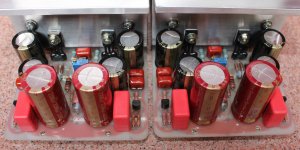
What a beautiful babies.Hi Abetir,
I'm on my way too...
this VSSA with K246GR & J103GR...
it's took me years to source thoose parts 😀
btw, how to tune the VAS current?
I've power it on with lower supply & measure the current
it was 20mA on vas & maybe it is too much
Regards
John

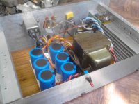
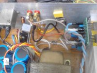
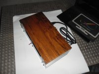
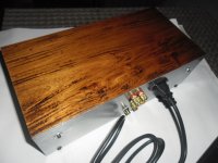
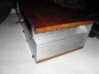
My poormans VSSA chassis, (in mono, traffo is not enough for a stereo to drive a pair of 200w 6ohms speakers 😛)
Attachments
Last edited:
Do not use protect speakers??
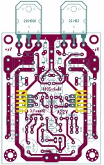
My pcb.
My pcb.
An externally hosted image should be here but it was not working when we last tested it.
Last edited:
I have omitted the 10uf bypass caps (very expensive in my place 🙁)
Hi if you include the 10 µF caps and make a new PCB version with them I will send them for free. Wima MKS 2 or 4.
2 PCBs for me please 😉
Do not use protect speakers??
I had to say that I am not so comfortable with the protect circuit as I have a "not so good" experience with it. Having it, DC offset was bit higher than without it, so I detached the thing 🙁 My VSSA has been playing for months without DC protect and is rock stable and totally silent even at power on and off. I even have a softstart before but also removed the thing. I guess the EMI filter (rated 6amps 250v) could do the job of limiting the AC mains current. 🙂
Nice boards by the way, 😎
Hi if you include the 10 µF caps and make a new PCB version with them I will send them for free. Wima MKS 2 or 4.
2 PCBs for me please 😉
Hi jean-paul!
As much as I wanted to furnish you with factory made boards using my design, I have no means of producing them here in my place. I could however revise my boards per your request and post the files here (including gerbers). Perhaps anyone who is capable and wanted to have a factory made board can go ahead with the job.

Best regards.
Hi jean-paul!
As much as I wanted to furnish you with factory made boards using my design, I have no means of producing them here in my place. I could however revise my boards per your request and post the files here (including gerbers). Perhaps anyone who is capable and wanted to have a factory made board can go ahead with the job.
Best regards.
Hey I made the promise so I will keep it. When you add the 10 µF then also make the input cap a 10 µF film type while you are at it 😉. If there is a board house where you live then .... you could do a Group Buy....

BTW which software do you use for layouts ?
- Home
- Amplifiers
- Solid State
- VSSA Through-Hole-PCB build thread