VSSA
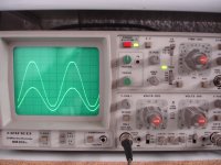
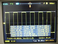
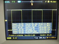
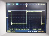
First two photos .
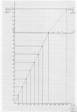
1) start clipping
2) Heavy clipping.
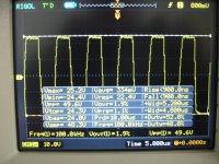
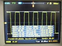
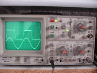
Other photos .
See on screan.
All tests with
+/-35v
36.000uf/rail
150mA VAS
2mA inp.
0v offset.
Without R,L added
Preheating time 1h.
First two photos .
1) start clipping
2) Heavy clipping.
Other photos .
See on screan.
All tests with
+/-35v
36.000uf/rail
150mA VAS
2mA inp.
0v offset.
Without R,L added
Preheating time 1h.
Attachments
Last edited:
 ...
...First two photos .
1) start clipping
2) Heavy clipping.
Other photos .
See on screan.
All tests with
+/-35v
36.000uf/rail
150mA VAS
2mA inp.
0v offset.
Without R,L added
Preheating time 1h.
please read: 150mV ON 10R SO VAS current is 15mA SORRY for this mistake.
R dummy=8x1R/17W.
Last edited:
VSSA
Hi John truth is that i haven't so good speakers in my laboratory.
It's so difficult to listen difference in such good amplifiers.
In any case sound is very good.
Give me some time🙂
Regards.
Thimios.
Hi John truth is that i haven't so good speakers in my laboratory.
It's so difficult to listen difference in such good amplifiers.
In any case sound is very good.
Give me some time🙂
Regards.
Thimios.
Hi John truth is that i haven't so good speakers in my laboratory.
It's so difficult to listen difference in such good amplifiers.
In any case sound is very good.
Give me some time🙂
Regards.
Thimios.
Enjoy

Thimios my friend excelend job.
Now must construct B1 buffer then you listening difference between amps.
http://www.diyaudio.com/forums/pass-labs/124889-b1-buffer-preamp-387.html#post3675396
Now must construct B1 buffer then you listening difference between amps.
http://www.diyaudio.com/forums/pass-labs/124889-b1-buffer-preamp-387.html#post3675396
Hi my friend,thank you.Thimios my friend excelend job.
Now must construct B1 buffer then you listening difference between amps.
http://www.diyaudio.com/forums/pass-labs/124889-b1-buffer-preamp-387.html#post3675396
Yes of course i will look at this.
Best regards.
Thimios.
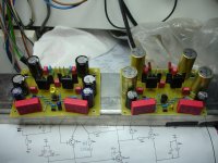

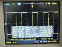
I have try this 2nd channel with 22pf smd compensation.
I don't think that this is stable with 22pf only not even with 44pf(2x22pf).
I don't think that this is stable with 22pf only not even with 44pf(2x22pf).
Attachments

Last edited:
I have try this 2nd channel with 22pf smd compensation.
I don't think that this is stable with 22pf only not even with 44pf(2x22pf).
Hi thimios info seen from the various VSSA threads says that is it BD VAS devices nothing or less compensation needed, and if the higher speed KSA/KSC VAS devices 22pF and up needed. But as seen you have nice equipment to pick best comp. Good soldering
Hi Ricky i have used ksa/ksc in 1st and 2nd board.
In 1st board compensation capacitors are 47pf. ampl. is stable.
2nd board tested with 22pf smd and is unstable,then 44pf(2x22pf) unstable again.
Next step is replacing smd cap. with these same type.47pf as in 1st board.
Regards.
Thimios.
In 1st board compensation capacitors are 47pf. ampl. is stable.
2nd board tested with 22pf smd and is unstable,then 44pf(2x22pf) unstable again.
Next step is replacing smd cap. with these same type.47pf as in 1st board.
Regards.
Thimios.
Last edited:
Hi Ricky i have used ksa/ksc in 1st and 2nd board.
In 1st board compensation capacitors are 47pf. ampl. is stable.
2nd board tested with 22pf smd and is unstable,then 44pf(2x22pf) unstable again.
Next step is replacing smd cap. with these same type.47pf as in 1st board.
Regards.
Thimios.
Try not to use smd caps. It's easy to damage them with electrostatic and soldering iron. Keep using good old TH components.
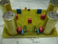
Sorry to interrupt you guys, I have built VSSA v1.4 (LCs original) I have changed a few components from the original schematic. I have used BC556B for the input diff, 2SC3600/SA1406 for VAS with 47pf comp caps, 2SK246 for ccs and FR diodes for the MURs. I am temporarily using 1uf caps for the 10uf decoupling cap at the input, and now I'm stuck. I managed to get almost 0mv DC offset (by using 2k trimpots on the ccs fets) but I am getting around 1v of white noise? 0scillations? The audio out is very faint and distorted drowned by tremendous humming. Touching the inputs results to a loud hum in the speakers, guess this is normal. The voltage rail is stable at -/+36vdc, but why is the audio out so poor? 😕
I'm hoping anyone of you can help me out. Thanks!
I'm hoping anyone of you can help me out. Thanks!
Attachments

Wonderfull try i think and nice build at picture. I am not a pro please have this in mind, but hope my info is some kind usefull...........
I'm hoping anyone of you can help me out. Thanks!
LC's version is setup at higher bandwith than other VSSA versions, therefor layout, compensation, component choice can tease.
Two things seen in picture, first the two feedback caps 2.2mF from schematic v1.4 shall be at least 1mF but best to be 2,2mF. This said because in picture looks like very small cap you have there. Second take out that 1uF bipolar, only don't use at all or use the recommended 10uF. Link here to good info what can happen here http://www.diyaudio.com/forums/powe...ing-psu-capacitors-effective.html#post1566979.
If using voltage reference IC, remember it's TLVH431 and not TLV431.
Here link for good comments from LC to another build her in thread http://www.diyaudio.com/forums/soli...ugh-hole-pcb-build-thread-36.html#post3804129.
PS If you get lost, think if you gear down the feedback network to component values that is in PMI schematic here in thread post #1 you would have your build up running playing music.
Last edited:
Silly question but you mention using BC556B at the input but no mention of its compliment, the BC546B, so you do realize the input is not a pair of BC556Bs but one each BC556B and BC546B?
Sorry to interrupt you guys, I have built VSSA v1.4 (LCs original) I have changed a few components from the original schematic. I have used BC556B for the input diff, 2SC3600/SA1406 for VAS with 47pf comp caps, 2SK246 for ccs and FR diodes for the MURs. I am temporarily using 1uf caps for the 10uf decoupling cap at the input, and now I'm stuck. I managed to get almost 0mv DC offset (by using 2k trimpots on the ccs fets) but I am getting around 1v of white noise? 0scillations? The audio out is very faint and distorted drowned by tremendous humming. Touching the inputs results to a loud hum in the speakers, guess this is normal. The voltage rail is stable at -/+36vdc, but why is the audio out so poor? 😕
I'm hoping anyone of you can help me out. Thanks!
Many thanks guys,
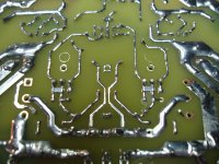
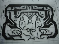
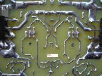
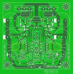
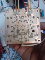
The two feedback blue caps are actually 10v 2.2mf but on my shunt regulator it was a TLV431AC not TLVH431. I have skimmed both datasheets and it looks similar to me but then I could be wrong, not an expert here too 🙂. The PCB was Dacz work (another member) I modified it for use with 2SK246 at the CCS, pin designation are different from the recommended 2Ns in LCs schematic. I do remember LCs earlier comments on my error on 2SKs PCB tracks and I was hoping I did it correctly this time. The input diff was in pair BC556B and BC546B (sorry 'bout that ). I have attached Dacz earlier PCB work for use with the 2SK246 fets perhaps if somebody could show to me how to properly connect the SGD pins, I could then compare it with my PCB build if I've done it correctly. (sorry I do not have my modified lay-out I only did the track modification using a permanent marker before etching) I'm still confused here. Bottom copper track pics also attached.
Thank you for the link BYRTT, that is one extensive info
Kind regards!
(kindly disregard the click image, can't remove the thing)
Attachments
- Home
- Amplifiers
- Solid State
- VSSA Through-Hole-PCB build thread