vssa
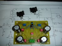
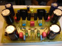
Now on the test bed!
Just listening and the first observation....
A little hum just heard when my ear is on speaker(with shorted input).
+/-35V
36.000uf/rail.
Now on the test bed!
Just listening and the first observation....
A little hum just heard when my ear is on speaker(with shorted input).
+/-35V
36.000uf/rail.
Attachments

Last edited:
Hi Thimios,
I'm sure you'll be impressed at the first time...
I'll be waiting your impression 😉
please be careful when you tune it,
it is should be easy to get zero offset
Best Regards
John
I'm sure you'll be impressed at the first time...
I'll be waiting your impression 😉
please be careful when you tune it,
it is should be easy to get zero offset
Best Regards
John
Hi dear ...yes it's easy to get zero offset but this (zero) isn't so stable...Hi Thimios,
I'm sure you'll be impressed at the first time...
I'll be waiting your impression 😉
please be careful when you tune it,
it is should be easy to get zero offset
Best Regards
John
Do you match the input pair? maybe it can help...
please put zobel network too, I don't see it yet in your board
Please do, if you don't want to get some oscillation 🙂
please put zobel network too, I don't see it yet in your board
Please do, if you don't want to get some oscillation 🙂
Last edited:
Yes input pair is matched ,as for zobel this is the first "fire test".😉Do you match the input pair? maybe it can help...
please put zobel network too, I don't see it yet in your board
Please do, if you don't want to get some oscillation 🙂
Thanks for reply.🙂
Hi dear ...yes it's easy to get zero offset but this (zero) isn't so stable...
Hi thimios, very nice handmade build you have there.
If the unstable offset continues after calibration and heatup I have a suggestion. In some other application i have used the same flexible sockets as you use for the input pair and got some unstability, this went away by soldering devices directly to PCB. Not to say but it's a possibility.


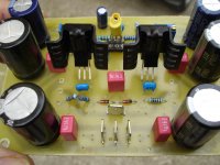
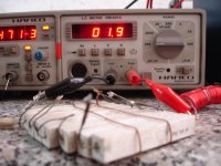
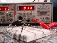
vssa
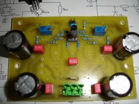
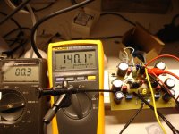
Vas bias adjust. 14mA
Offset 0mV
+/-35V
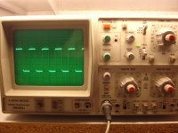
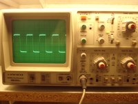
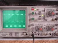
Strange is that ampl.is stable with speaker(4R) but anstable with dummy load (8X1R/17W Res.).
Scopes without load 2KHz ,10KHz,20KHz.
Vas bias adjust. 14mA
Offset 0mV
+/-35V
Strange is that ampl.is stable with speaker(4R) but anstable with dummy load (8X1R/17W Res.).
Scopes without load 2KHz ,10KHz,20KHz.
Attachments
Last edited:
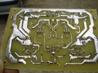
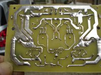
Hi thimios. In PeeCeeBee thread we saw little metal pieces wrapped around input pair making fluctuations when not grounded.
It's a widebander amp, below point 1 and 2 could make difference, and point 3 of less importance but worth a try.
1. Try on one channel direct solder your matched input pair with shorter legs than you have now.
2. Make ground potential at heatsink, it's a cap and antenna for amp module.
3. Guess VAS heatsinks are isolated from device, try make ground potential.
Hi thimios. In PeeCeeBee thread we saw little metal pieces wrapped around input pair making fluctuations when not grounded.
It's a widebander amp, below point 1 and 2 could make difference, and point 3 of less importance but worth a try.
1. Try on one channel direct solder your matched input pair with shorter legs than you have now.
2. Make ground potential at heatsink, it's a cap and antenna for amp module.
3. Guess VAS heatsinks are isolated from device, try make ground potential.
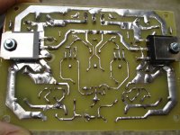
Hi Byrtt i will try all these tomorrow.As i can see vas heatsinks are not in ground in PMI original pcb.
Regards.
Last edited:
Hi thimios. In PeeCeeBee thread we saw little metal pieces wrapped around input pair making fluctuations when not grounded.
It's a widebander amp, below point 1 and 2 could make difference, and point 3 of less importance but worth a try.
1. Try on one channel direct solder your matched input pair with shorter legs than you have now.
2. Make ground potential at heatsink, it's a cap and antenna for amp module.
3. Guess VAS heatsinks are isolated from device, try make ground potential.
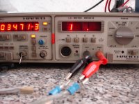
All these tried today but without result.
ampl oscillate on dummy load.
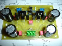
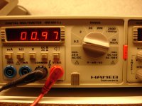
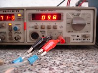
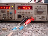
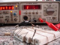
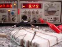
About these photos.
1)dummy inductance.
2) >> resistance
3) >> capacitance
4) speaker resistance
5) >> inductance
6) >> capacitance.
As i have mentioned in previous message this ampl. is stable on speaker but unstable on this dummy.
Attachments
Last edited:
Hi thimios
Few advices:
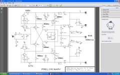
- your amp is probably HF under compensated, try to trimm Miller caps to optimal value
- your dummy load has a reactive part of impedance too high
- your connecting cables are too capacitive
- try to use RL filter in series with +SPK wire (1 uH inductor in parallel to 4,7 Ohm/2W resistor)
- decoupling film caps too far away
- your PCB layout is at question, especially feedback path
Your measuring gear is OK, so there should be no trouble to solve problems.
Few advices:
- your amp is probably HF under compensated, try to trimm Miller caps to optimal value
- your dummy load has a reactive part of impedance too high
- your connecting cables are too capacitive
- try to use RL filter in series with +SPK wire (1 uH inductor in parallel to 4,7 Ohm/2W resistor)
- decoupling film caps too far away
- your PCB layout is at question, especially feedback path
Your measuring gear is OK, so there should be no trouble to solve problems.
Hi lazy Cat thanks for reply.Hi thimios
Few advices:
- your amp is probably HF under compensated, try to trimm Miller caps to optimal value
- your dummy load has a reactive part of impedance too high
- your connecting cables are too capacitive
- try to use RL filter in series with +SPK wire (1 uH inductor in parallel to 4,7 Ohm/2W resistor)
- decoupling film caps too far away
- your PCB layout is at question, especially feedback path
Your measuring gear is OK, so there should be no trouble to solve problems.
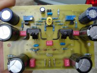
Miller capacitors are 47pf ,PMI has good results with 22pf only.
My connecting cable with dummy are two short separate wires .
I tried R,L, this shown in photo.
Decoupling capacitors position and pcb is same as PMI original.
Thanks again for help.
Best regards.
Thimios.
Attachments
Last edited:
Maybe stupid but could those 47pF by accident be 4,7pF.Hi lazy Cat thanks for reply.
Miller capacitors are 47pf ,PMI has good results with 22pf only.
..........
Maybe stupid but could those 47pF by accident be 4,7pF.
I have measure these 47pf before assembling.
Is on my plan to replace these with 47pf styroflex type.
Last edited:
VSSA
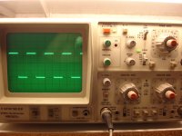
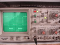
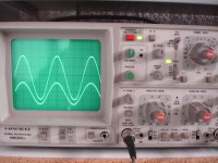
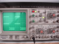
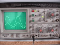
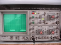
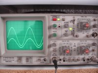
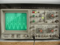
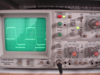
Problem solved or no problem at all....
As i have mentioned oscillation occurred only on dummy load but not on real speaker.
This because there is a ground loop at test equipments.
Signal generator ground and oscilloscope ground .
When oscilloscope ground removed all is ok.
Now it's time for more tests.
First set photos.
1KHz ,10KHz,20KHz,50KHz,100KHz sin.& squar.
Up.output
Down:input
Attachments
-
 DSC07395.JPG589.5 KB · Views: 107
 -
 DSC07394.JPG604.3 KB · Views: 107
 -
 DSC07393.JPG590.8 KB · Views: 91
 -
 DSC07392.JPG573.2 KB · Views: 105
 -
 DSC07391.JPG601.3 KB · Views: 105
 -
 DSC07389.JPG592.2 KB · Views: 107
 -
 DSC07388.JPG605.7 KB · Views: 118
 -
 DSC07387.JPG521 KB · Views: 115
 -
 DSC07386.JPG549.3 KB · Views: 126
 -
 DSC07396.JPG579.6 KB · Views: 132
Last edited:
- Home
- Amplifiers
- Solid State
- VSSA Through-Hole-PCB build thread