How much current flows in the VAS transistors??
Yesterday I tested only outputs with resistor divider providing Vgg and current was stable at 440 mA, so outputs with fixed Vgg (voltage drop on resistor) have stable bias completely.
VAS current set to 15 mA, very stable (14,5-15,5 mA) before employing bias to outputs.
When both running on the same heatsink, PTC is obvious, so output bias is going up because 2SA/SC gain is rising with temperature.
I will check with reference zener (1-100 mA shunt regulator) as bias spreader so the outputs will have constant Vgg, meaning constant bias, no matter of VAS current fluctuations. In that way cumulative process will be avoided, VAS bias will stop rising at certain temperature.
I will check with reference zener (1-100 mA shunt regulator) as bias spreader so the outputs will have constant Vgg, meaning constant bias, no matter of VAS current fluctuations. In that way cumulative process will be avoided, VAS bias will stop rising at certain temperature.
TLVH431BQ adjustable precision shunt regulator from 1,24 to 18V, 100uA to 70mA, -40 to +125°C temperature range, most suitable to replace bias trimmer for ALF mosfet. In this way Vgg and therefore output bias current will stay constant as once set, regardless of VAS bias current variation. In this case 2SA/SC could stay on the main heatsink to ensure smallest PCB possible. 😎
Hello
I used to have similar problem with these topology. Especially with higher bias.
All do I never mount the VAS to the main heatsink.
wahab made some change in the circuit, I want to see if that will improve the stability.
Also I'm interested how you guys succeed to resolve these issue.
The frustrating think to me the Darlington I used the best sounding amplifier I built over 22 years or so.
Soon I will test the Lat FET version..
I want to hear if will be difference sound wise between the darlington and the FET.
Greetings Gabor
TLVH431BQ adjustable precision shunt regulator from 1,24 to 18V, 100uA to 70mA, -40 to +125°C temperature range, most suitable to replace bias trimmer for ALF mosfet. In this way Vgg and therefore output bias current will stay constant as once set, regardless of VAS bias current variation. In this case 2SA/SC could stay on the main heatsink to ensure smallest PCB possible. 😎
Yes this part fixes the bias problem, but still the bias of the VAS transistors Will be highly depending of the heatsink temperature.
Yes this part fixes the bias problem, but still the bias of the VAS transistors Will be highly depending of the heatsink temperature.
I'll check the range of VAS bias. The good thing is it won't go below initial setting. 😀
The frustrating think to me the Darlington I used the best sounding amplifier I built over 22 years or so.
Soon I will test the Lat FET version..
I want to hear if will be difference sound wise between the darlington and the FET.
Greetings Gabor
Hi Gabor
I suggest you to use ALF mosfets, they have low Cgs and high transconductance. I couldn't find better ones for the job in this simple topology. Also they're stocked in Farnell or Newark (Element 14).
I'm sure you'll be pleased with the sound with these new parts incorporated. 😉
Soon I will test the Lat FET version..
I want to hear if will be difference sound wise between the darlington and the FET.
I will keep my ears up for any sound comments 😀
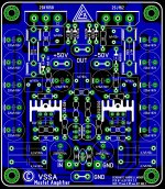
VSSA has 6 transistors.
That qualifies in my book as very simple.
Do I have to read past post1 to discover that it becomes very complicated SA later?
I started reading the SSA and TSSA and had to give up with both because both completely forgot the topic of the Threads ! SIMPLE
That qualifies in my book as very simple.
Do I have to read past post1 to discover that it becomes very complicated SA later?
I started reading the SSA and TSSA and had to give up with both because both completely forgot the topic of the Threads ! SIMPLE
This is the latest published version.VSSA has 6 transistors.
That qualifies in my book as very simple.
Do I have to read past post1 to discover that it becomes very complicated SA later?
I started reading the SSA and TSSA and had to give up with both because both completely forgot the topic of the Threads ! SIMPLE
It is in post #128
http://www.diyaudio.com/forums/solid-state/225747-vssa-lateral-mosfet-amplifier-3.html#post3298495
It is still simple.
VSSA has 6 transistors.
That qualifies in my book as very simple.
Do I have to read past post1 to discover that it becomes very complicated SA later?
I started reading the SSA and TSSA and had to give up with both because both completely forgot the topic of the Threads ! SIMPLE
Well.. The TSSA first couple of schematics are very simple and they works.
Hi AndrewDo I have to read past post1 to discover that it becomes very complicated SA later?
No, not in the VSSA thread. I promised it will stay fixed on six transistors with parts needed to assure stability and safety. The last V1.2 sch posted is pretty much final. You can assemble one if you like. 😉
Last edited:
Hi,
Nice little amp.
 🙂
🙂
My
Importance of feedback resistor tolerance. How about positive and negative transfer functions, perfectly equal? Why not trim one feedback resistor in relation to the other? Great opportunity to 'zero' distortion.
Nice little amp.
My
Importance of feedback resistor tolerance. How about positive and negative transfer functions, perfectly equal? Why not trim one feedback resistor in relation to the other? Great opportunity to 'zero' distortion.
Hi AKN 
Actually it is possible to trimm-out distortions by observing minimal subtraction product of equalized input/output signal. That can we do as a strawberry on a cake, bonus in a finalizing process.
Actually it is possible to trimm-out distortions by observing minimal subtraction product of equalized input/output signal. That can we do as a strawberry on a cake, bonus in a finalizing process.

Cordell audio has various models available, including those you seek. http://www.cordellaudio.com/book/spice_models.shtml
- Home
- Vendor's Bazaar
- VSSA Lateral MosFet Amplifier