Ok, I will say it differently:
Hi lazy cat
In case it was not clear for everybody:
What do you think of a VSSA lateral amp topology using a MOSFET instead of BJT for VAS?
Fab
Hi Fab
VSSA is locked at the moment to sch and PCB intended for GB, very detaily specified and tested, so no room for any changes.
Of course there can be mosfet, IGBT, BJT, tube in the second TIS/VAS stage but that is some otherday's story, OK?
Regards, Andrej
P.S. Can we just leave the VSSA thread as it is to bring it safely to GB deliveries.
As you all know VSSA with linear PSU, presented two weeks ago, is working hard each and every day. I push it just below clipping for many hours every day, so far no problems detected, output DC offset is locked at + 3 mV on L and + 5 mV on the R channel, output bias fixed to 160 mA. I really want to bring the exact copy of mine VSSA amp quality to all GB members, trouble free of course. 
New VSSA PCB almost assembled, both channels will be finished tomorrow, two SMPS400 already here, ready to be put into action. Over the weekend new VSSA will be tested with SMPS 400 PSUs, report will follow. 😉
New VSSA PCB almost assembled, both channels will be finished tomorrow, two SMPS400 already here, ready to be put into action. Over the weekend new VSSA will be tested with SMPS 400 PSUs, report will follow. 😉
Hello Lazy. What about the lower idle current of 20 - 40 mA.
It is just if someone would build an active speaker the heat generated could be reduced a lot this way. 3 amps for 3 elements would generate roughly the same as on running at 120 - 160mA.
It is just if someone would build an active speaker the heat generated could be reduced a lot this way. 3 amps for 3 elements would generate roughly the same as on running at 120 - 160mA.
Hello Lazy. What about the lower idle current of 20 - 40 mA.
It is just if someone would build an active speaker the heat generated could be reduced a lot this way. 3 amps for 3 elements would generate roughly the same as on running at 120 - 160mA.
I understand exactly what you mean, I have here K+H O300, which have three amp channels inside, each dedicated to specific driver, and heatsink behind is pretty warm.
Well VSSA works with that little bias, that's for sure, but it would be suboptimal, also Semelab recommends 110 mA per mosfet pair. One would have to try and measure/listen the result of lower output bias.
Lazy Cat ...OK, its your call, and your amp !
Nice, thank you tinitus.

I have tested with this low bias also. And it worked well for me, just that there is enough and fast enough predriver.
As you all know VSSA with linear PSU, presented two weeks ago, is working hard each and every day. I push it just below clipping for many hours every day, so far no problems detected, output DC offset is locked at + 3 mV on L and + 5 mV on the R channel, output bias fixed to 160 mA. I really want to bring the exact copy of mine VSSA amp quality to all GB members, trouble free of course.
New VSSA PCB almost assembled, both channels will be finished tomorrow, two SMPS400 already here, ready to be put into action. Over the weekend new VSSA will be tested with SMPS 400 PSUs, report will follow. 😉
Hello LC,
thanks for your effort to check this.
If you push the amp this hard, what is the temperature of the heatsink ?
Hello LC,
thanks for your effort to check this.
If you push the amp this hard, what is the temperature of the heatsink ?
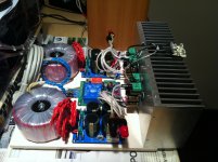
As you know or just look to pic, heatsink is overkill, so never goes over 50°C. 😎
This VSSA I am doing now will be separated and smaller ones, so will be tested to higher temp too. But nevertheless bias cannot go higher it is locked with TLVH431, no matter the temp. It actually goes down a little if pushed hard, since ALF has negative tempco. 😉
Attachments
I have tested with this low bias also. And it worked well for me, just that there is enough and fast enough predriver.
Yes, TIS/VAS has to have at least 12 mA bias and KSA/KCS are just perfect for the job, very pleased with them.
As you know or just look to pic, heatsink is overkill, so never goes over 50°C. 😎
sure hope it stays below 40degr into normal impedance load
50degr should only be into 2ohm 😀
btw, is it tested into low impedance load ?
As you know or just look to pic, heatsink is overkill, so never goes over 50°C. 😎
Hi LC, over what your experiment, what level heatsink really need one VSSA chanel in worst case?
Regards marc
As you know or just look to pic, heatsink is overkill, so never goes over 50°C. 😎
...I had hoped for this since I want to put four amp modules in one enclosure.
🙂 In the BOM you specified 0,4 K/W, SK-157. This is the one in your picture, no?
you specified 0,4 K/W, SK-157.
SK-157 is one of the toughest heatsink profiles around
very thick 12mm base and nice long 75mm finning
how much you need really only depends on length
'length' is what you might consider 'height'
but there might be other more 'compact' heatsink profiles
with this amp especially I suppose its good to have a 'fast' heatsink
which I reckon would be 'compact'...whatever that might be
maybe highest possible K/W rating at smallest possible area 😕
Hi LC,
How much power a SMPS must have to support a two channel VSSA Amp in 4 Ohms ?
Thank you.
How much power a SMPS must have to support a two channel VSSA Amp in 4 Ohms ?
Thank you.
Summer time 32°C inside hot appartment, no air conditioner present, 4 ohm speakers and you have a party, each sec clipping present at 40 Vp ... now calculate. Even the one in pic would be too small. 😀Hi LC, over what your experiment, what level heatsink really need one VSSA chanel in worst case?
Regards marc
Yes, exactly....I had hoped for this since I want to put four amp modules in one enclosure.
🙂 In the BOM you specified 0,4 K/W, SK-157. This is the one in your picture, no?
Heatsink really depends on how hard an amp will be pushed, for how long and at which speaker's impedance. Safest solution is overkill heatsink like in the pic. It is really working properly, hot air flow is very obviously present, whenever I lean over to check if amp is OK. The temp is always below 50°C, so if one decide to choose smaller heatsink the temp will inevitably go up, for how much, it is subjective calculation/choice.

btw, 50degr heatsink is very hot, and more like Pass F5 classA
you will not like to touch it for more than few seconds
my 50watt do that when driving 2ohm speaker
or else just mildly warm
try measure water when washing hands, and you will know how hot it is
for 4 channels I would suggest 150-200mm SK-157
but modu shop makes very nice affordable box well suited for this amp
one 'stereo' box will do 4 channels nicely
buying quality heatsinks like this seperately tend to be way too expencive
buying a heatsink seperately, I would only recommend that for classA
btw, forum shop/store may be worth a look
Summer time 32°C inside hot appartment, no air conditioner present, 4 ohm speakers and you have a party, each sec clipping present at 40 Vp ... now calculate. Even the one in pic would be too small. 😀
Sad news...have to salvage fridge to build VSSA casing.....🙄
Marc
Hi LC,
How much power a SMPS must have to support a two channel VSSA Amp in 4 Ohms ?
Thank you.
Well, look to SMPS's maximal output current capability, that counts. SMPS400 gives app. 5 A to 8 A max at something like 6 V voltage drop from unloaded condition, since this SMPS is unregulated. And that is just barely enough for one VSSA channel, which ALF can conduct 8 A max continuous drain curent.
The best would be to use 400 W regulated SMPS, will test that too, probably with Coldamp 80SMPS or SMPS2000R from Connex.
The worst power dissipation in a class B amplifier is around : Vs²/20.RL Where Vs is rail voltage, and RL, your charge (Plus the quiescient power dissipation).
With an output voltage of Vrms=0.225*Vs.
With an output voltage of Vrms=0.225*Vs.
- Home
- Vendor's Bazaar
- VSSA Lateral MosFet Amplifier