on the note of heat sinks, may be a little lateral thinking may help. I'm going to use passive cooling with heat pipes and fins, like used in computers. Other idea is a Peltier device, could be sophisticated, so transistors are always at a constant temperature.
Last edited:
the p channel ALF08P16V came today from Farnell, the N channels are in transit, in another envelop, go figure!!. Yet another reason to buy them as a dual package, either you get them, or you don't! 😡
Does this mean that +ve and -ve transistors travel at different speeds? Ain't Physics wonderful.
Does this mean that +ve and -ve transistors travel at different speeds? Ain't Physics wonderful.
Very bad idea, omho: efficiency is very poor, and you will have to dissipate a lot of extra calories for no benefit.Other idea is a Peltier device, could be sophisticated, so transistors are always at a constant temperature.
The problem, with computers is the little surface of CPUs vs high power, and the fact that overclock depends of the temp.
In analog amplifiers, we are in a different situation: We just need silence, and to keep our power devices inside their safe area. Easy to fulfill with passive radiator witch will add a nice thermal inertia.
If you want to use heat pipes, beware the fact that the temp of the device will be "regulated" by the boiling temperature of the coolant inside, usually kinda high, around 60°.
50° is not a high temp for a passive radiator..
the p channel ALF08P16V came today from Farnell, the N channels are in transit, in another envelop, go figure!!. Yet another reason to buy them as a dual package, either you get them, or you don't! 😡
Does this mean that +ve and -ve transistors travel at different speeds? Ain't Physics wonderful.

Hi Fab
VSSA is locked at the moment to sch and PCB intended for GB, very detaily specified and tested, so no room for any changes.
Of course there can be mosfet, IGBT, BJT, tube in the second TIS/VAS stage but that is some otherday's story, OK?
Regards, Andrej
P.S. Can we just leave the VSSA thread as it is to bring it safely to GB deliveries.
No offense but This thread special "rules " are too complicated for my little brain. I thought that there was a specific section of the forum for GB to prevent polluting the technical threads.... I also thought that moderators would check for that too but I may be wrong there....
I prefer the "open" technical discussion thread.
Thanks anyway for sharing that design to the DIY community.
Fab
Last edited:
Hi Fab 
No special rules here, only one and that is: all in one thread, just to be more simple and to have better control and faster response time to any request. GB in this thread is so benign that its list is hardly noticable in between discussion and it doesn't bother anybody. That means that even if no GB would take place here I wouldn't be satisified with more than one VSSA version since that was a promise given to Bigun at the begining. VSSA is locked to the lowest parts count possible and at the same time achieving the best quality possible. And what a quality! I guarantee you if you'll ever build VSSA, it would probably be the last amp you'll ever made. From my plentiful practical experiences it simply surpasses all VFB amps with left hand, just as simply as passing by.
So if you still want to develop the VSSA variant further on, please start a new thread like Shaan did already.
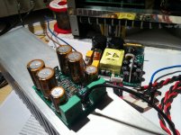
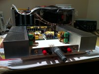
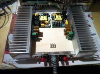
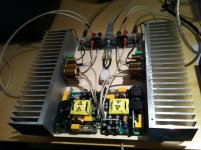
I was a little short in time this wekend, to finish complete prototype of VSSA + SMPS400 amplifier as I promised, but anyway it will happen tomorrow hehehe. 
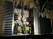
Both VSSA channels finished today, mounted on separate heatsinks, calibrated, measured and tested in combination with SMPS400 at +/-45 V and I have to tell you all that I'm really really pleased. So far all together four VSSA channels built and capability of reproducibility is very constant, no surprises at all.
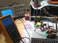
To all CFB amplifier's sceptics I can only say: forget the VFB. Two major specifications they always bring to daylight are DC stability and PSSR. My answer here would be: VSSA has 1 mV stable output DC offset (pic 3.) no mater the temp, from cold start to heavy loading programme, no DC offset stability problem noticable whatsoever. Of course no DC servo present around. PSSR is unmeasurable with my FLUKE-TEK measuring equipment. Also no hiss, hum, pop up, bang, boom on/off sounds from speakers, zero, nada. 😀
Few pics of the measuring session attached.
Both VSSA channels finished today, mounted on separate heatsinks, calibrated, measured and tested in combination with SMPS400 at +/-45 V and I have to tell you all that I'm really really pleased. So far all together four VSSA channels built and capability of reproducibility is very constant, no surprises at all.
To all CFB amplifier's sceptics I can only say: forget the VFB. Two major specifications they always bring to daylight are DC stability and PSSR. My answer here would be: VSSA has 1 mV stable output DC offset (pic 3.) no mater the temp, from cold start to heavy loading programme, no DC offset stability problem noticable whatsoever. Of course no DC servo present around. PSSR is unmeasurable with my FLUKE-TEK measuring equipment. Also no hiss, hum, pop up, bang, boom on/off sounds from speakers, zero, nada. 😀
Few pics of the measuring session attached.
Attachments
Last edited:
Congratulations Lazy cat!!! a very well done amp!😉
Thank you lanchile. 😉 VSSA gives me a great enjoyment in listening the music. :cloud 9:
What was the goal in this amp?
To be better performer than any other amp, in home environment of course. 😀
Sonnya,
Low bias with lateral mosfets is OK. Manufacturers recommend c. 100mA bias just to coincide with zero tempco of lateral mosfets, to be sure that you shall always have negative tempco. But unlike BJTs that have nasty under and over bias artefacts following loud passges, Lateral mosfets are not critical with biasing at all and are in fact very benign for biasing. 20-40mA is fine and I think that LC should include in instructions for VSSA kit resistor values for low bias. I also do not intend to use big SK157 heatsink, but much smaller SK92 because my loudspeakers are of high sensitivity (92dB) and I never listen music very loud.
Low bias with lateral mosfets is OK. Manufacturers recommend c. 100mA bias just to coincide with zero tempco of lateral mosfets, to be sure that you shall always have negative tempco. But unlike BJTs that have nasty under and over bias artefacts following loud passges, Lateral mosfets are not critical with biasing at all and are in fact very benign for biasing. 20-40mA is fine and I think that LC should include in instructions for VSSA kit resistor values for low bias. I also do not intend to use big SK157 heatsink, but much smaller SK92 because my loudspeakers are of high sensitivity (92dB) and I never listen music very loud.
Hi guys
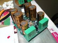
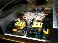
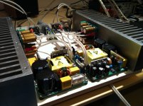
VSSA + SMPS400 already playing for few hours now hehe
It looks Nichicons doing their job pretty well. HR files are pure pleasure to listen to, just music.
VSSA + SMPS400 already playing for few hours now hehe
It looks Nichicons doing their job pretty well. HR files are pure pleasure to listen to, just music.
Attachments
Congratulation.
Any difference with your linear psu version ?
During this week we will make a comparative test...buzzing vs switching power supplies 😀
- Home
- Vendor's Bazaar
- VSSA Lateral MosFet Amplifier