VSSA is always appropriate! 🙂
Don't have the full description of your system, so I only assume you will have 2 VSSA for each channel, and use bi-wiring. Woofers on one set of amps and higher frequency components on another set.
From the manual of LS80 I can see: a 2500Hz at 24db/octave for high frequencies and a 400Hz crossover between woofers of 6dB/octave, meaning (probably) a ~50uF cap in series with (probably the top) one of the woofers. Even while keeping them like that (no paralleling directly) you still should consider around 6,5OHMS to be the load for that amplifier, increasing while decreasing the frequency below 400Hz. (I considered your 13OHMs to be the woofer impedance, as previously stated by you).
That's a pure approximation, the exact value depends on the loudspeaker construction as well (but I am not good on loudspeakers design, so i will stay with this approximation). But the load will never be 13 OHMS, unless we are talking DC.
If you want to modify the internal filters, that might be different. Anyway it's better to specify how you want to use the amplifiers/speakers combination, in order to receive effective help. Also you might want to check your existing filters to avoid assumptions like mine, which may be not true.
Cheers!
My tip: Just compensate your speakers with a passive network in order to get a flat impedance curve (motional + zobel). Resulting impedance to be the DC resistance for each. As an example, my 2426 JBL drivers (announced like 16 ohms) just make 6 ohms (their dc resistance), once compensated.
My system ? 5 speakers: 1sub (JBL2224H) +2x 2Ways (boomer +horn) . 1 400W class D amp, 2X 200W, 2VSSA+DCX2496.
My system ? 5 speakers: 1sub (JBL2224H) +2x 2Ways (boomer +horn) . 1 400W class D amp, 2X 200W, 2VSSA+DCX2496.
Last edited:
Now I have a question for the wise: can the VSSA be modded to work with quasi-complementary output??
The thing is that I have some Semisouth (enhancement) units lying around unused...
Thank you very much.
M.
It looks like some people have done that, just have a look with some translation services:
Quasi-VSSA
But the symmetry is gone if you do that.
Cheers!
It looks like some people have done that, just have a look with some translation services:
Quasi-VSSA
But the symmetry is gone if you do that.
Cheers!
Thank you!
Having Google translator with listening capacity is a good thing! 😀
I don't see too much loss of symmetry, if you do the "Szicklai" pair at both sides, just two more BJT, plus one more if the Semisouth have positive tempco, which I don't remember...
Am I the only one interested in this approach??? 😕
Cheers,
M.
just an update, I will finally use my 4 VSSA for mids and highs, and I will use Roberto's SDA-400 for the 4 woofers
http://www.diyaudio.com/forums/vend...00-professional-multi-way-17.html#post3721125
seems he has some stock left for promotion if you guys want to go same way as I 🙂
also will try his DPS400 SMPS with VSSA @ 42V then. Let see 🙂
http://www.diyaudio.com/forums/vend...00-professional-multi-way-17.html#post3721125
seems he has some stock left for promotion if you guys want to go same way as I 🙂
also will try his DPS400 SMPS with VSSA @ 42V then. Let see 🙂
Thank you!
Am I the only one interested in this approach??? 😕
Cheers,
M.
I am interested in any approach of VSSA. I just don't have enough time to try them 🙁 If you want to go that path of quasi, please let us know the outcome.
Cheers!
You'll have a perfect system with the best of the two worlds. Notice that class D amps have something, in their transparency, the way to reproduce sounds an easy way, with space for little details of the same family than good current feedback amps. And VSSA is a VERY good CFA.I will finally use my 4 VSSA for mids and highs, and I will use Roberto's SDA-400 for the 4 woofers
I am interested in any approach of VSSA. I just don't have enough time to try them 🙁 If you want to go that path of quasi, please let us know the outcome.
Cheers!
I am also short of free time at this years' end 🙁 of course I will post and ask for help, it's only that I fear my lacl of knowledge...
Checked: positive tempco, so 9 transistors will be needed, one for Vbe multiplier. Vgs threshold is low (even lower than K1058/J162) typical 1V, MIN 0,75V. Protection zener diodes will be fitted.
Any recommendations are welcome.
Last edited:
SB ZxR-ARTA measuring system for the First One
Being busy lately putting together measuring system for testing forthcoming First One amplifier modules. For that reason I assembled PC with SB ZxR audio card and the results are Quite impressive.
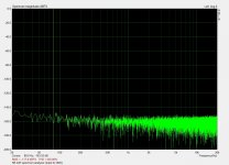
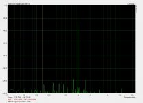
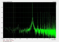
Spectrum analyser and signal generator formed by combining SB ZxR plus ARTA sofware are very capable one, just for an example of their performances three images are attached.
1. noise floor of an input shorted to GND
2. noise floor of an opened input
3. 1 kHz test sine from signal generator has just 0,0002% THD
Being busy lately putting together measuring system for testing forthcoming First One amplifier modules. For that reason I assembled PC with SB ZxR audio card and the results are Quite impressive.
Spectrum analyser and signal generator formed by combining SB ZxR plus ARTA sofware are very capable one, just for an example of their performances three images are attached.
1. noise floor of an input shorted to GND
2. noise floor of an opened input
3. 1 kHz test sine from signal generator has just 0,0002% THD
Attachments

Very impressive, and congratulation with new toy. How does card sound. Maybe i am stupid, but wonder that the input output converters range 120-127dB, how can you measure so deep.
It probably sounds nice, the only reason I bought it is to measure and compare different HF compensation methods on First One to get best performance to sound result. It will just serve to record and compare spectral signatures to find the best possible signature, such info would be also very helpful to develop any future designs.
ZxR card itself has 124dB signal to Noise Ratio (20kHz Low-pass filter, A-Wgt), more here. 😉
ZxR card itself has 124dB signal to Noise Ratio (20kHz Low-pass filter, A-Wgt), more here. 😉
Hehe... the best is when miller cap (if any) is fed... lowZ... direct from output, right ?It probably sounds nice, the only reason I bought it is to measure and compare different HF compensation methods on First One to get best performance to sound result
They have put complicated names for this ;-)
Last edited:
hahaha just tested my old Elektor signal generator - sine 1 kHz 😱
Maybe you should mod your signal generator and put a VSSA type output section on it 😀
Congratulations for your new amp!
M.
Hi All...
I need to find some transistors to replace the 2sa1381/2sc3503. I ruined mine while desoldering them because I forgot the plastic washers 🙁
I've tried all the usual places: Digikey, Mouser, Farnell, etc. but nowhere has any stock.
PMI has kindly offered to send me some; however, I think he is busy with other things and hasn't been around the forum lately.
So can anyone recommend a (hopefully easily available) substitute?
- Home
- Vendor's Bazaar
- VSSA Lateral MosFet Amplifier