What ? for now it's just a simulation
Do you have the last VSSA lateral schematic with real component in place of CCS ?
Thankks
Do you have the last VSSA lateral schematic with real component in place of CCS ?
Thankks
Last edited:
The fetZilla : (for the VAS)
http://www.diyaudio.com/forums/atta...n-fetzilla-power-amp-fetzilla-schematic-5.pdf
http://www.diyaudio.com/forums/atta...n-fetzilla-power-amp-fetzilla-schematic-5.pdf
Last edited:
show what ?
😀
I cannot remember what
😀
by the way, what needs improvement in above schematic?
To reduce non-linear distortion, replace R20 and R15 on the generators. You will increase the gain. Further increase the depth of feedback.
Thanks FEDOSOFF but the last schematic is not on the first page but on post 44
Do you think is it possible to use CSS in vas on this schematic ?
Do you think is it possible to use CSS in vas on this schematic ?
UltimateX86 you achieve the minimum distortion or want to get a good sound.Thanks FEDOSOFF but the last schematic is not on the first page but on post 44
Do you think is it possible to use CSS in vas on this schematic ?
The output stage is necessary to make a composite - Sziklai. At the entrance a small field-effect transistor. At the output of bipolar. This bundle when the experiment gave - 10 volt output. The Load Is 4 Ohms. The quiescent current of 1.5 amps. The supply voltage of 27 Volts, the total harmonic distortion of the output stage 0.00054%. Without General feedback. Balanced signal will need to bring a Converter current - voltage. Directly from the resistor of the Converter. With respect.Sound !
The quiescent current of 1.5 amps is so much for me ... but could you made a schematic ?
Jfet differential input ?
CFP BJT output stage like your schematic with mosfet ?

http://www.diyaudio.com/forums/soli...stabilization-system-modes-3.html#post4121252
Jfet differential input ?
CFP BJT output stage like your schematic with mosfet ?
http://www.diyaudio.com/forums/soli...stabilization-system-modes-3.html#post4121252
Last edited:
Last edited:
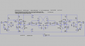
Here is my fast & provisional schematic with inserted follower (Q3) which allow to drive multiple output power LatFets , only half of the Amp is showed , but you have to find where lower side of follower emitter res. ( Re) is best rail point to connect , on the speaker rail , on the B- rail ,or even on the ground rail .
( BTW I like that generic simple VSSA Circlotron design with only two output power N type LatFets .since I deal with 16ohm (load)speaker )
For shure that it is possible to acomodate that VAS on your VSSA Circlotron project , it is look nice with that CCS on VAS collector side , any way try to simulate this schematic to .
Hello, I dont simulate your schematic for the moment but I'll do this weekend
Hi UltimateX86
Try to replace R20 & R15 (RC) with suitable two CCS , or divide both R20 & R15 and insert two bootstrap electrolytic caps in between of that divided res.networks.
Best Regards !
What is better, CSS or bootstrap ?
What is better, CSS or bootstrap ?
Theoretically CCS is better solution ,
but personally I prefer bootstrap since I can play with different value of bootstrap capacitor to find optimum sound performance.
And check this very unique A class SS Circlotron design , where input cascoded LTP work with balanced current GNFB .http://www.diyaudio.com/forums/solid-state/270239-i-call-infinitron.html
- Status
- Not open for further replies.
- Home
- Amplifiers
- Solid State
- VSSA Circlotron