I'm thrilled that diyAudio members are building their own VRDN. It's quite a beast; not many linestage PSUs work well and deliver low noise / low ripple when the load current is 1.5 amps.
Also: don't forget to conduct a subjective human judgement experiment. Which sounds better to your ears? With, or without, the shorting bars that disable/enable the DeNoiser circuits?
Also: don't forget to conduct a subjective human judgement experiment. Which sounds better to your ears? With, or without, the shorting bars that disable/enable the DeNoiser circuits?
I was very happy to find this design with the CRC before the regulator and the de-noiser after. Anything better would be very hard to build, this was very easy. I'm going to use it with a Waynes BA 2018 linestage bumped up to 20dB gain. Should be a perfect match. Also had the snubber on the transformer output. I did go ahead and measure the MOV in my Quasimoto with the .68 cap. I needed a 10 ohm resistor instead of the 33 ohm to get the ringing to subside. I'm using a 100VA Antek AS-1218. This stuff is addictive.
EU-based board order?
I'd love two boards please, if/when someone next has some available. Preferably EU-based (it makes the money transfer and shipping easier), but US also works.
I'd love two boards please, if/when someone next has some available. Preferably EU-based (it makes the money transfer and shipping easier), but US also works.
Hi all.
I recently finished building the aleph J from the store (and it sounds fantastic).
I need a decent preamplifier for it, that's why I bought the pcb and the components to mount a BA 2018 in the diyaudio store. My idea is to use this PSU to power it, and I was wondering if I could sign up for the next order of the pcb, or else if there is any other way to get it.
greetings and thank you very much to all the users who make possible the approach to good hi-fi in this very creative way. (excuse my "english", I am and live in Spain)
Question 1N400 Which one?
Hi!
I'm filling my basket, but have a little issue here:
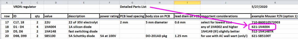
D1 - D4 are supposed to be 1N4004, 1A silicon diode, Mouser# 621-1N4004
Mouser offers me either 1N4004-T or 1N4004G-T.
Do I go with the 1N4004G-T (the other being "not recommended for new design")?
Hi!
I'm filling my basket, but have a little issue here:
D1 - D4 are supposed to be 1N4004, 1A silicon diode, Mouser# 621-1N4004
Mouser offers me either 1N4004-T or 1N4004G-T.
Do I go with the 1N4004G-T (the other being "not recommended for new design")?
Last edited:
Doesn’t matter. Get whichever. And order extras, you always need diodes in these projects, may as well have a few more in hand...
NRND just means they won’t be building that specific variant anymore, it’s most likely going to have a part number change.
NRND just means they won’t be building that specific variant anymore, it’s most likely going to have a part number change.
Doesn’t matter.
Perfect, thank you, 6L6!
(I guessed it was something like this, but guessing isn’t the best bet [emoji848])
For my Eurorack projects, I keep about 6 types of diodes lying around. They are usually pretty cheap, so buying both and/or extras usually just ends up saving me time and money down the road.
D1 - D4 are supposed to be 1N4004, 1A silicon diode, Mouser# 621-1N4004
Look inside the blue rectangle and also look inside the yellow rectangle.
Choose the one whose part number is 621-1N4004.
_
Attachments
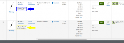
> 1N4004, ..... 1N4004-T or 1N4004G-T.
"G" seems to be Lead-free. Non-G is discouraged in some markets. However there is a lot of old stock.
"T" seems to mean "Tape"? This is critical if you have automatic insertion machines. One-off, does not matter.
"G" seems to be Lead-free. Non-G is discouraged in some markets. However there is a lot of old stock.
"T" seems to mean "Tape"? This is critical if you have automatic insertion machines. One-off, does not matter.
VRDN
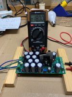
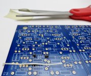
It rained all day in Shreveport, so no fence building. Took me about four hours to assemble the board. Checked the transformer then the transformer and power supply, using my handy dandy Dim Bulb Tester. Good test.
Mark thanks for all of the hard work to develop this Power Supply. Also thanks to RickRay for the board.
Someone somewhere said if there "ain't' pictures it didn't happen. Well here goes
Now if I can just get those "SMD" devices soldered to the BA2018.
Thanks everyone😀
Attachments

@A321Drvr -- Congratulations! And attaboy for the very nice pics. I recommend something a little more heatproof than cardboard, for a long term insert between the heatsinks. I use Kapton tape that I buy from Amazon and eBay, here's part of their sales blurb
_
_
Attachments
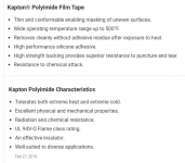

Corrugated "Kapton"
Hey Mark, and Pfarrell,
The cardboard is "Double Insulated Corrugated".
I do in fact have some Kapton Tape on the way.
Sometimes you have to adapt and overcome using some good ole "Red Neck Engineering". I did put my beer on the table behind me while I placed the said Cardboard gently between the heatsinks.
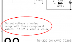
Please notice the voltages mentioned in the title of this thread:
and the VRDN schematic diagram (attached to post #1 of this thread) agrees. ±20V is as high as it will go, when your turn the trimmer potentiometers all the way clockwise.
I suppose that a highly motivated & enthusiastic reader might be able to modify the circuit design to give higher output voltages. However I think it is probably not an easy task; the very first job would be to read through Elvee's Forum thread about his De-Noiser circuit, and learn whether it works or fails at 24V output. (I don't know the answer, myself). Also to learn whether Elvee recommends any component value modifications in the frequency compensation sections of the De-Noiser, to preserve stability.
Another job the modification team would need to do, is re-calculate the necessary voltage, current, and power limitations when the output voltage is higher. Maybe the heatsinks called for in the Parts List are simply inadequate? Maybe the specially called-out 600 milliwatt resistors need upsizing? What about the large number of 2200uF filter capacitors? What about the Metal Oxide Varistors? And so forth.
It would be a not-insignificant amount of effort and there is a chance that the final answer might be: don't do this, it cannot work. But highly motivated & enthusiastic people are also highly optimistic, so I wish you happy designing and best wishes for complete success!
_
VRDN: bipolar regulator PCB for line level ckts: ±11V to ±20V @ 1.5A with "De-Noiser"
and the VRDN schematic diagram (attached to post #1 of this thread) agrees. ±20V is as high as it will go, when your turn the trimmer potentiometers all the way clockwise.
I suppose that a highly motivated & enthusiastic reader might be able to modify the circuit design to give higher output voltages. However I think it is probably not an easy task; the very first job would be to read through Elvee's Forum thread about his De-Noiser circuit, and learn whether it works or fails at 24V output. (I don't know the answer, myself). Also to learn whether Elvee recommends any component value modifications in the frequency compensation sections of the De-Noiser, to preserve stability.
Another job the modification team would need to do, is re-calculate the necessary voltage, current, and power limitations when the output voltage is higher. Maybe the heatsinks called for in the Parts List are simply inadequate? Maybe the specially called-out 600 milliwatt resistors need upsizing? What about the large number of 2200uF filter capacitors? What about the Metal Oxide Varistors? And so forth.
It would be a not-insignificant amount of effort and there is a chance that the final answer might be: don't do this, it cannot work. But highly motivated & enthusiastic people are also highly optimistic, so I wish you happy designing and best wishes for complete success!
_
Attachments
- Home
- Amplifiers
- Power Supplies
- VRDN: bipolar regulator PCB for line level ckts: ±11V to ±20V @ 1.5A with "De-Noiser"