I plan to cut mine down to four fins and see if that's OK
That's what was done in post 8, and what I should have done. Oops! Fortunately I found a seller (arrow.com) that will ship heatsinks plus a few X1 caps with free shipping from the US(!). So I'll do the same.
I don't think there's a problem with them touching the case since the devices are insulated from the sinks via the insulator pads and shouldered washers. Could be totally wrong though!
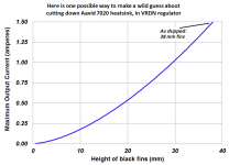
If you are brave and if you trust your own instincts, you can use the frequently employed engineering practice called Rectal Extraction. It is one way to make a guess about what happens when you reduce the Aavid 7020 heatsink height.
First you choose a derating curve, by pulling an equation out of a moist dark place.
Then you program the curve (equation) into Excel, and plot it.
Then you look at the plot and decide whether it does, or does not, match your instincts. What do YOU think happens when you cut off part of the heatsink? Put it into numbers. Then plot it.
An illustrative BUT NO DOUBT TERRIBLY WRONG example is shown below. I pulled an intentionally nonsense equation out of the muckpile and into the daylight. Then I plotted it. You can do the same. Then decide whether you do or don't trust the predictions you have made.
_
Attachments

If you are brave and if you trust your own instincts, you can use the frequently employed engineering practice called Rectal Extraction. It is one way to make a guess about what happens when you reduce the Aavid 7020 heatsink height.
First you choose a derating curve, by pulling an equation out of a moist dark place.
Then you program the curve (equation) into Excel, and plot it.
Then you look at the plot and decide whether it does, or does not, match your instincts. What do YOU think happens when you cut off part of the heatsink? Put it into numbers. Then plot it.
An illustrative BUT NO DOUBT TERRIBLY WRONG example is shown below. I pulled an intentionally nonsense equation out of the muckpile and into the daylight. Then I plotted it. You can do the same. Then decide whether you do or don't trust the predictions you have made.
_
Well I guess that's better than pulling numbers out of your a$$.
Wait a second...
Found my answer on post #57 and #58.Hello guys!
Before building the board, is 50VA dual 18V (Antek) good for +- 20 ? Is 25VA enough?
I am planning to use it for BA18 and Mesmerize supply. Thank you!
abe
Thanks Mark for identifying a process I have long suspected was very common but now it has a proper name it seems more reputable...what does it sound like in latin?If you are brave and if you trust your own instincts, you can use the frequently employed engineering practice called Rectal Extraction. It is one way to make a guess about what happens when you reduce the Aavid 7020 heatsink height.
First you choose a derating curve, by pulling an equation out of a moist dark place.
Then you program the curve (equation) into Excel, and plot it.
Then you look at the plot and decide whether it does, or does not, match your instincts. What do YOU think happens when you cut off part of the heatsink? Put it into numbers. Then plot it.
An illustrative BUT NO DOUBT TERRIBLY WRONG example is shown below. I pulled an intentionally nonsense equation out of the muckpile and into the daylight. Then I plotted it. You can do the same. Then decide whether you do or don't trust the predictions you have made.
_
Seriously though, I think we can all appreciate that reducing the size of the specified heatsink by 30% will reduce the cooling effect on the regulator. Is this significant if one is using the VRDN to drive one or even two BA18 boards ? Fitting the board into a 1U enclosure seems to be a very reasonable intention as all other components including suitable transformers make that possible. So the question is either...is the reduction in cooling consequential ? Or are there more efficient heat sinks that would fit the board and chassis dimensions. Does the Kapton tape reduce cooling efficiency and if so , could that be dispensed with ?
I know its frustrating for designers when people fiddle with, customize or hack their well considered design solutions, but is there a possible non-rectal approach to this ?
Well I guess that's better than pulling numbers out of your a$$.
Wait a second...
If you are not going to drive a low impedance load such as headphones with the BA2018, then you are looking at maybe 100mA per board X4 = 400mA.
Since you are then at a little less than a third of the original heat sink design capacity of 1.5A, my personal SWAG (scientific wild a$$ guess) and (allowing for a non-linear relationship of surface area to dissipation) is that you should be okay. Probably.
I'd say, invest in a $20 no contact temperature measurement gun, build with the sinks you have and take readings. If you are below 60 deg C at the device, they should enjoy a long and happy life. If you are serious about DIY and at all into class A, the temp gun is a great investment.
Link to current draw of BA2018 (post 1460): https://www.diyaudio.com/forums/pass-labs/329240-waynes-ba-2018-linestage-146.html#post6303863
raising the temp
That seems like a laudably sensible approach....heat gun winging its way from Amazons cloud and I can also use it to check the heatsink temp on Class A amps....thanks
That seems like a laudably sensible approach....heat gun winging its way from Amazons cloud and I can also use it to check the heatsink temp on Class A amps....thanks
Connecting the beast
Now I've got to admit it again:
I'm a bit scared to bungle with the wiring of the VRDN...
I've got:
2 Pcs. Toroidy TTSA0050 Audiograde 2 x 18V 50VA
2 VRDN
1 BA-18 Linestage.
While the threads were developing (parts were already ordered) I realized that 1 transformer and 1 VRDN would be plenty (correct?)
The transformer has as secondaries 2 browns / 2 whites, specified as "sec.1: 18 V brown-brown, sec.2: 18V white-white.
Although it seems crystal-clear that I just have to read the PCB (sec.1 / sec.2), it actually IS correct, isn't it? (And, my logic tells me that it then can't matter which of the wire's comes first?)
For the variations, IF I was to use both transformers on 1 VRDN's, how'd I connect them then?
And if I used both VRDN's?
I know I'm a bit demanding here, sorry.
thanks!
david
Attachments

I don't think you'd want/need to connect two transformers to one VRDN. If you use two VRDNs (for dual mono) then using one transformer for each makes sense I think. BTW, I bought 18Vx2 50VA transformers and I'm wondering if I went too small. 🙂
As I understand it, you would connect one secondary to one terminal (e.g. white, white to W and X) and the other to the other (e.g. brown, brown to Y and Z).
Then, to connect the VRDNs to the BA2018, one PSU would power each half of the preamp. From one VRDN connect OUT+, GND, and OUT- to V+, GND, and V- on one side of the BA2018. Do the same for the other VRDN and the other side of the BA2018.
Of course, before you connect the PSU(s) to the preamp you should probably test the PSU boards alone, with a dim bulb tester. If the bulb isn't glowing (40w?) after start up and you see reasonable voltages at the outputs then you can swap in a normal mains cable and tune the voltages to 18V (or whatever) with the trimmers. Then connect to the preamp board and try again with dim bulb just to be safe. If that seems ok then go back to a normal mains cable and do whatever calibration needs to happen on the preamp.
That's how I'd do it, but my only experience is an F5, universal PSU, soft start and speaker protection boards. The VRDNs and the BA2018 are my first builds without hand holding guides so I reserve the right to be totally wrong.
Anyway, hopefully someone can scan this and confirm my wiring description seems ok.
The VRDN design has the common ground after the rectification and the schematic does not indicate a preferred phase relationship between the transformer secondaries. So the hookup appears to be arbitrary, but I'm not sure the purpose of J0R1, 2 and 3 is affected by that relationship, maybe MJ can weigh in on that.
If the circuit design had 2 secondaries tied as if they were a single center tapped secondary, the AC phase relation between the two secondaries would definitely matter. Frankly, I'm shocked that Toroidy does not color code their leads to allow for use in that type of power supply design. Some inference can be made from the physical relationship in the way the leads break out from the wraps, but it is not a guarantee. It seems observation of the transformer secondaries using an oscilliscope would be required.
If the circuit design had 2 secondaries tied as if they were a single center tapped secondary, the AC phase relation between the two secondaries would definitely matter. Frankly, I'm shocked that Toroidy does not color code their leads to allow for use in that type of power supply design. Some inference can be made from the physical relationship in the way the leads break out from the wraps, but it is not a guarantee. It seems observation of the transformer secondaries using an oscilliscope would be required.
So the hookup appears to be arbitrary, but I'm not sure the purpose of J0R1, 2 and 3 is affected by that relationship, maybe MJ can weigh in on that.
The function of JOR1/2/3 is explained in the second image attachment of the first post. See the second row:
IIUC in this case secondary hookup doesn't matter because each secondary is connected to its own bridge rectifier.
Right - I forgot that 22meg was just a device required to represent an open circuit in the design program
I don't think you'd want/need to connect two transformers to one VRDN. If you use two VRDNs (for dual mono) then using one transformer for each makes sense I think. BTW, I bought 18Vx2 50VA transformers and I'm wondering if I went too small. 🙂
… connect one secondary to one terminal (e.g. white, white to W and X) and the other to the other (e.g. brown, brown to Y and Z).
[…]
The VRDNs and the BA2018 are my first builds without hand holding guides …
If the circuit design had 2 secondaries tied as if they were a single center tapped secondary, the AC phase relation between the two secondaries would definitely matter. Frankly, I'm shocked that Toroidy does not color code their leads to allow for use in that type of power supply design. Some inference can be made from the physical relationship in the way the leads break out from the wraps, but it is not a guarantee. It seems observation of the transformer secondaries using an oscilliscope would be required.
Yes, it seems strange to me too. Wonder what will happen with the bigger PSU once I get there.
OTOH, a new toy (oscilloscope) comes into the arena, which is good in itself 🙂
When you build a larger PSU (e.g. DiyAudioStore Universal), you'll either be building the rectification board, or you'll be using monolithic bridges. Either way you would be fine because each bridge will handle one secondary separately. So there's no issue with getting anything on the secondary side out of phase. The output of the bridges will be DC into the filtering board.
The more important part would be if you get a transformer with dual 115V primaries (one that can be wired to work with 115V and 230V mains) then you'll definitely need to get those in phase when putting them in series! But I couldn't imagine a transformer manufacturer not color coding primaries well.
The more important part would be if you get a transformer with dual 115V primaries (one that can be wired to work with 115V and 230V mains) then you'll definitely need to get those in phase when putting them in series! But I couldn't imagine a transformer manufacturer not color coding primaries well.
Is there a version with just one single positive supply?
There are two PCB designs with single positive rail in the original D-noizator thread.
Hi guys,
Do you see any potential problem if I use VRDN to power both BA2018 (18V) linestage and this (link nelow) to get +5V https://www.mouser.com/ProductDetail/CUI-Inc/PQDE6W-Q24-S5-T?qs=fAHHVMwC%252BbijFYVgeEIusg%3D%3D&gclid=Cj0KCQjw7ZL6BRCmARIsAH6XFDLfSQ_xsGziMn4sblj-arJpjGu2GbcDjb_7ZeEHNyXRYvj-IOR8DQAaAvSmEALw_wcB for https://www.muffsy.com/muffsy-relay-input-selector-4.html ?
Thank you!
Abe
Hi guys,
Do you see any potential problem if I use VRDN to power both BA2018 (18V) linestage and this (link nelow) to get +5V PQDE6W-Q24-S5-T CUI Inc. | Mouser for https://www.muffsy.com/muffsy-relay-input-selector-4.html ?
Thank you!
Abe
Why not use the IRM-05-5 breakout board for the muffsy to tap into the mains? Isolating the lower noise VRDN for your preamp circuit.
Attachments
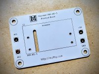
Yes, thank you! I forgot about that.Why not use the IRM-05-5 breakout board for the muffsy to tap into the mains? Isolating the lower noise VRDN for your preamp circuit.
- Home
- Amplifiers
- Power Supplies
- VRDN: bipolar regulator PCB for line level ckts: ±11V to ±20V @ 1.5A with "De-Noiser"