Thank you!Equations for peaking filter by RBJ. This is compatible with most of the DSP devices and apps:
Equations to calculate b0...a2 for Bell filter in Monacor DSP is needed.
I've contacted Monacor and AllDSP requesting the above information.
Does the software properly account for the filtered response when it comes to floor reflections?
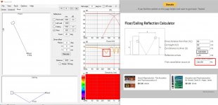
For example, I have a midrange driver that calculates out to having a first reflection at 500 Hz using this calculator:
https://mehlau.net/audio/floorbounce/
So, I want to high-pass the midrange sufficiently above this first reflection frequency so that I don't get the first (lowest) null within the midrange passband. But when I adjust the high-pass frequency to what seems to be a high enough frequency, it barely changes the null in the in-room response. The woofers I have below the midrange driver are so close to the floor that the first reflection is way above their passband, too.
Thoughts?
Member
Joined 2003
What if I stand up? what if I sit down? what if I sit somewhere else? What about the ceiling and walls? What if I move the speaker 6in to the left?
In any case, try clicking on the "room" tab in VituixCAD.
In any case, try clicking on the "room" tab in VituixCAD.
The following is just general thoughts - not response to previous. I can't recall clearly why boundary reflections were added to Diffraction tool and Room tab in the main program. Probably someone (Jack?) simulating line arrays asked and I did it knowing that I won't use or recommend boundary simulation for other than quick testing of quasi "infinite" line arrays.
Single boxed woofer close to floor is problematic in full space application because it initiates all possible vertical modes and should be crosser quite low (causing increased excess GD) in order to avoid problems also at XO range. More sustainable design is slightly (40...50 cm) elevated woofer or multiple woofers as a line array. Both with tilt in LF response so that power stays quite constant below predicted Schroeder frequency for example 100...150 Hz. Boundary simulation is not required.
I won't remove those features but please prefer designs which don't use and require simulation of some individual reflection.
Check out a interference test posted here https://www.diyaudio.com/community/threads/efficient-2-way.380822/page-5#post-6897205, it takes quite a lot of attenuation to get rid of interference between two signals. Basically either of the signals need to be attenuated ~20db, which is quite a lot. With 4th order filter you'd need to cross about 1 octave above the null! And it is not just the null (destructive interference), because there is constructive interference right next to it! If there was no destructive interference, you'd still have "null" since there is boost both sides of it due to constructive interference. This in mind, if one is concerned about the reflections (caused interference) it is very hard to tame it down locally and broad band control is needed = narrower directivity.Does the software properly account for the filtered response when it comes to floor reflections?
For example, I have a midrange driver that calculates out to having a first reflection at 500 Hz using this calculator:
https://mehlau.net/audio/floorbounce/
So, I want to high-pass the midrange sufficiently above this first reflection frequency so that I don't get the first (lowest) null within the midrange passband. But when I adjust the high-pass frequency to what seems to be a high enough frequency, it barely changes the null in the in-room response. The woofers I have below the midrange driver are so close to the floor that the first reflection is way above their passband, too.
Thoughts?
But as said, there are many nulls due to all boundaries in the room and the frequencies shift as you move, quite a lot. While you can sort of optimize a single first vertical reflections in theory it would only apply to very small position because as one moves the interference moves. And don't think just about the floor, path length difference through the ceiling is typically longer and interference starts lower in frequency than with floor. While these are very interesting phenomena to experiment in the simulator I think there is more practical value in Kimmosto suggestion, sort of lumping the individual reflections together and thinking/experimenting in broader sense, like thinking the room modes on long wavelengths and perhaps applying narrower directivity on shorter wavelengths.
I made some tests with delayed signal in headphones, and while this really does not correspond how room reflections would be perceived in room, since they come from different location instead of just one and there are many, it is pretty remarkable how the hearing system is able to get rid of the interference. It sounds pretty bad in headphones with one or multiple delayed signals no matter of the delays, unless multiple delayed signals with same delay, which combined "over power" the "direct" sound and the sound becomes almost nice again. Kind of interesting experiment in it self 🙂
Last edited:
Yes, the in-room response (orange line, on my default views/layout) is coming from the info that I entered into Room, with "Floor" checked off.What if I stand up? what if I sit down? what if I sit somewhere else? What about the ceiling and walls? What if I move the speaker 6in to the left?
In any case, try clicking on the "room" tab in VituixCAD.
Thanks kimmosto!The following is just general thoughts - not response to previous. I can't recall clearly why boundary reflections were added to Diffraction tool and Room tab in the main program. Probably someone (Jack?) simulating line arrays asked and I did it knowing that I won't use or recommend boundary simulation for other than quick testing of quasi "infinite" line arrays.
Single boxed woofer close to floor is problematic in full space application because it initiates all possible vertical modes and should be crosser quite low (causing increased excess GD) in order to avoid problems also at XO range. More sustainable design is slightly (40...50 cm) elevated woofer or multiple woofers as a line array. Both with tilt in LF response so that power stays quite constant below predicted Schroeder frequency for example 100...150 Hz. Boundary simulation is not required.
I won't remove those features but please prefer designs which don't use and require simulation of some individual reflection.
Yes, however, even with almost an octave "over" the crossover frequency (using LR24) the in-room response barely changes. Based on kimmosto's post it's possible the simulation is not entirely accurate when it comes to the floor reflection vs relative driver position vs passbands... may take a bit of fooling around with the physical implementation.Check out a interference test posted here https://www.diyaudio.com/community/threads/efficient-2-way.380822/page-5#post-6897205, it takes quite a lot of attenuation to get rid of interference between two signals. Basically either of the signals need to be attenuated ~20db, which is quite a lot. With 4th order filter you'd need to cross about 1 octave above the null! And it is not just the null (destructive interference), because there is constructive interference right next to it! If there was no destructive interference, you'd still have "null" since there is boost both sides of it due to constructive interference. This in mind, if one is concerned about the reflections (caused interference) it is very hard to tame it down locally and broad band control is needed = narrower directivity.
But as said, there are many nulls due to all boundaries in the room and the frequencies shift as you move, quite a lot. While you can sort of optimize a single first vertical reflections in theory it would only apply to very small position because as one moves the interference moves. And don't think just about the floor, path length difference through the ceiling is typically longer and interference starts lower in frequency than with floor. While these are very interesting phenomena to experiment in the simulator I think there is more practical value in Kimmosto suggestion, sort of lumping the individual reflections together and thinking/experimenting in broader sense, like thinking the room modes on long wavelengths and perhaps applying narrower directivity on shorter wavelengths.
I made some tests with delayed signal in headphones, and while this really does not correspond how room reflections would be perceived in room, since they come from different location instead of just one and there are many, it is pretty remarkable how the hearing system is able to get rid of the interference. It sounds pretty bad in headphones with one or multiple delayed signals no matter of the delays, unless multiple delayed signals with same delay, which combined "over power" the "direct" sound and the sound becomes almost nice again. Kind of interesting experiment in it self 🙂
Yeah the woofer is then responsible for the dip, did you check the heights, Y coordinates for your drivers? As the crossover is significantly above the dip then the dip is on the woofers bandwidth and if the woofer is at same height (and Z) as mid the dip doesn't move.
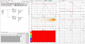
It looks like everything works as it should by few tests, calculator and VCAD show same frequency for first dip :
Ideal drivers coinsident, the first dip happens at the woofers bandwidth:
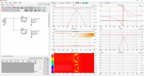
Here woofer is set -400mm, so path length through floor shortens in comparison to direct sound and the dip moves up in frequency like it should. This is roughly 605Hz in the calculator and in the VituixCAD the dip is roughly 580Hz so there is some difference.
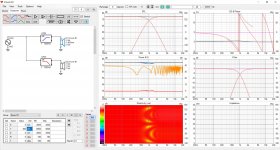
Here is for fun, the tweeter part moved up while woofer stays at 90cm. First dip is back at ~344Hz because it is the woofers bandwidth not the tweeters.
To get rid of the interference one should have directivity control, limit sound towards the angle on the floor.
As bonus here is fun GIF with crossover frequency changing from 100 > 1000Hz, as the low bandwidth changes form the higher up driver to the lower one, path length difference towards listening spot shortens and the dip travels up in frequency but almost nothing happens to the dips depth as expected because the directivity is (about) the same all the time. Around ~400Hz the dip gets a bit less since the 40cm c-c is roughly around half wavelength there and there is some directivity towards the reflection point on the floor, at least that what it looks like. Note how the constructive interference gets less as well above the first dip, the directivity due to c-c distance has most effect perhaps wavelength around 600Hz (by eyeballing) because we are inspecting the system through reflection at angle, not directly above or below in which case the reduction of interference would be at the ~400Hz.
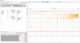
The constructive interference, and path length difference instead of just driver height, makes this phenomenon quite unintuitive!😀 Luckily we don't have to care about it much, other than if there is willingness to care, just narrow the directivity.
It looks like everything works as it should by few tests, calculator and VCAD show same frequency for first dip :

Ideal drivers coinsident, the first dip happens at the woofers bandwidth:

Here woofer is set -400mm, so path length through floor shortens in comparison to direct sound and the dip moves up in frequency like it should. This is roughly 605Hz in the calculator and in the VituixCAD the dip is roughly 580Hz so there is some difference.

Here is for fun, the tweeter part moved up while woofer stays at 90cm. First dip is back at ~344Hz because it is the woofers bandwidth not the tweeters.

To get rid of the interference one should have directivity control, limit sound towards the angle on the floor.
As bonus here is fun GIF with crossover frequency changing from 100 > 1000Hz, as the low bandwidth changes form the higher up driver to the lower one, path length difference towards listening spot shortens and the dip travels up in frequency but almost nothing happens to the dips depth as expected because the directivity is (about) the same all the time. Around ~400Hz the dip gets a bit less since the 40cm c-c is roughly around half wavelength there and there is some directivity towards the reflection point on the floor, at least that what it looks like. Note how the constructive interference gets less as well above the first dip, the directivity due to c-c distance has most effect perhaps wavelength around 600Hz (by eyeballing) because we are inspecting the system through reflection at angle, not directly above or below in which case the reduction of interference would be at the ~400Hz.

The constructive interference, and path length difference instead of just driver height, makes this phenomenon quite unintuitive!😀 Luckily we don't have to care about it much, other than if there is willingness to care, just narrow the directivity.
Last edited:
I will have to give it a shot later, but for me, I remember putting the woofers right at floor level so they should not have had any significant cancellation in the same region.
Hello,
I am setting up a dedicated speaker measurement area in my basement and am looking for advice on a new computer to use just for measuring.
My main desktop that I have been using for several years is an Intel i7-3770 CPU @3.40 Ghz with 16GB RAM with Win 7.0 64 bit.
Without breaking the bank, what CPU and RAM would you suggest to speed up VituixCAD from my current configuration?
I am assuming I will have to go with Windows 10 or 11.
Thank you,
David.
Member
Joined 2003
Hi Dave,
Measurement and simulation does not require any special hardware, a bottom of the line entry level PC will do the job just fine. If your current PC is somehow "slow" for VituixCAD work, I would look at other aspects of the OS installation other than the hardware. I do most of my VituixCAD work in a VM that I only provide 2 cores and 4GB of RAM.
For measuring a laptop is much more convenient, just make sure you have at least 1920x1080 display, you will not be satisfied with 1366x768. I love screen space, for my home PC I use an ultra wide 3440x1440 display and its wonderful.
Last edited:
Development and testing laptop is HP ZBook 17, Intel Core i7 2.8 GHz, 16 GB RAM, 500 GB SSD.
Windows 10 Pro 64-bit. CPU is too old for W11.
Windows 10 Pro 64-bit. CPU is too old for W11.
Excuse the stupid question but is this program able to automatically create a crossover if you input measured on and off-axis data?
No. Few library blocks are available for passive and active 2- and 3-ways, and optimizer supports iteration of block attributes suct as XO frequency and Q factor too. Any project can be used as starting point/template for other project. Ideal flat axial response can be created for active FIR using IR file. That is closest to designing XO producing ideal flat minimum phase response in a minute. So program is primarily versatile pro. Not for very beginners who don't know how XO components and blocks work.
Besides, it's very debatable if such a thing is even desirable.
Unless you will bake in some rule check (like an autorouter in PCB design) to ignore or force certain parts.
Certain dips should be left alone and compromises always have to be made.
Some choices are kind of subjective as well.
Unless you will bake in some rule check (like an autorouter in PCB design) to ignore or force certain parts.
Certain dips should be left alone and compromises always have to be made.
Some choices are kind of subjective as well.
No. Few library blocks are available for passive and active 2- and 3-ways, and optimizer supports iteration of block attributes suct as XO frequency and Q factor too. Any project can be used as starting point/template for other project. Ideal flat axial response can be created for active FIR using IR file. That is closest to designing XO producing ideal flat minimum phase response in a minute. So program is primarily versatile pro. Not for very beginners who don't know how XO components and blocks work.
kimmosto, Is there a tutorial on how to create an active FIR filter from a passive design? I saw the section in the document, but not able to understand 100% how to do it.
Use the passive filter response as your reference and just match the two.kimmosto, Is there a tutorial on how to create an active FIR filter from a passive design? I saw the section in the document, but not able to understand 100% how to do it.
Although, I wonder why you want to create a FIR from a passive filter?
Passive filter responses are far less ideal.
I thought about doing this for 'auralization' of a candidate passive xover. spit out FIR filters that match the transfer function of the passive xover, and then run that through a multi-amp setup to make experimenting/voicing/dialing in more efficient before finally committing the design to hardware. No idea whether this is what jmpsmash is doing though.Use the passive filter response as your reference and just match the two.
Although, I wonder why you want to create a FIR from a passive filter?
Passive filter responses are far less ideal.
Use the passive filter response as your reference and just match the two.
Although, I wonder why you want to create a FIR from a passive filter?
Passive filter responses are far less ideal.
I thought about doing this for 'auralization' of a candidate passive xover. spit out FIR filters that match the transfer function of the passive xover, and then run that through a multi-amp setup to make experimenting/voicing/dialing in more efficient before finally committing the design to hardware. No idea whether this is what jmpsmash is doing though.
Yes exactly my thought too. It will provide a quick prototyping of how the passive filter is going to sound. It will provide a quick turnaround between tweaking a value and actually able to hear it. It won't replace the final building up of the actual passive network but hopefully it will help arriving at a "best" one quicker.
Oh right, yeah it will give you some idea.I thought about doing this for 'auralization' of a candidate passive xover. spit out FIR filters that match the transfer function of the passive xover, and then run that through a multi-amp setup to make experimenting/voicing/dialing in more efficient before finally committing the design to hardware. No idea whether this is what jmpsmash is doing though.
You only won't get the dynamic interaction from a passive filter with the woofer.
- Home
- Design & Build
- Software Tools
- VituixCAD