^Maybe a single wire from generator to driver?
Is so, please read manual couple of times, watch youtube lessons, load my example projects, play with example projects for a week or two, read measurement preparation document few times, purchase valid measurement gear, build turning table.
Is so, please read manual couple of times, watch youtube lessons, load my example projects, play with example projects for a week or two, read measurement preparation document few times, purchase valid measurement gear, build turning table.
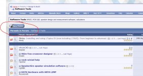
Couldn't find "Post New Thread"
Having a problem with VituixCAD. I load a driver, then the frd files, but nothing shows on any of the graphs but a few straight lines. What am I doing wrong?
Having a problem with VituixCAD. I load a driver, then the frd files, but nothing shows on any of the graphs but a few straight lines. What am I doing wrong?

User must select what measurement data in Drivers tab each driver instance in crossover is using. Driver is linked to measurement data by model name with combobox above Parameters grid in Crossover tab. Linking is done when each driver instance in the crossover has also name in the label e.g. "D2 ER18RNX".
I'm thinking that maybe 'Drivers' tab should be renamed to "Measurements". User should not think that component number (D1,D2,..) links to measurement data. You can have e.g. line array of 30 drivers in the crossover, and all of those are using the same measurement data in Drivers tab.
I'm thinking that maybe 'Drivers' tab should be renamed to "Measurements". User should not think that component number (D1,D2,..) links to measurement data. You can have e.g. line array of 30 drivers in the crossover, and all of those are using the same measurement data in Drivers tab.
Last edited:
Mooly: I've been in many forums and the 'New Thread' button is usually right where you show it. I think I could find that. It isn't there for me. There must be some waiting period.
I have selected a driver, ...put in it's name, ...added in the specific frd files, ...and the impedance file.....yet nothing shows on the graphs but lines.
^^What do you have in crossover? If you have a wire or some low Z component from generator to driver, you better send frd and zma files to me by e-mail. Address is in the end of DIY Loudspeakers Kimmo Saunisto
I haven't touched the Crossover tab yet. After watching a video, that person didn't bother with the Crossover area before he acquired and played with the freq. responses. That's what I want to do first.
^Ok. You can't get acoustic or electrical responses without connection from generator to driver. Some youtube videos (also mine) are for obsolete version 1.1. The latest video is for 2.0.
See also message #561.
See also message #561.
Mooly: I've been in many forums and the 'New Thread' button is usually right where you show it. I think I could find that. It isn't there for me. There must be some waiting period.
Can you try it now. I've released you from newbie status.
Can you see the new Thread button now ?
How to attach images:
How to attach images to your posts.
Sound22Card, the new thread button only appears when you are browsing a forum, not when you are in a thread. If you go back to the software tools forum you should see new thread, in the place where you see "post reply" in your attached screenshot.
Tony.
Tony.
Kimmo,
I have been playing around with version 2 for a couple of hours now and I have to say:
it is becoming FANTASTIC software!!! many thanks for this!
One request which would be very useful for better polar response design; user defined ranges for the directivity plot (so I could set the range for instance from 0 to 45 degrees)
The current+-180 deg. is a bit too course for my taste.
This would be highly appreciated.
many thanks,
Kees
I have been playing around with version 2 for a couple of hours now and I have to say:
it is becoming FANTASTIC software!!!
many thanks for this!One request which would be very useful for better polar response design; user defined ranges for the directivity plot (so I could set the range for instance from 0 to 45 degrees)
The current+-180 deg. is a bit too course for my taste.
This would be highly appreciated.
many thanks,
Kees
^You can and must limit sector with Half space checkbox in Options window if measurement data does not cover >90...180 deg. That limits also visible range of Polar map and other directivity charts to -90...+90 deg.
But generally, skipping of 90-180 deg is bad decision because is hides final tilt of power response. With dynamic dipoles and especially speakers having different polar pattern for different ways, 90-180 deg is almost mandatory.
But generally, skipping of 90-180 deg is bad decision because is hides final tilt of power response. With dynamic dipoles and especially speakers having different polar pattern for different ways, 90-180 deg is almost mandatory.
Can i use SPL trace to get the zma file from this image? The impedance scale makes it a little tricky. I tried linear and logarithmic both of which give me incorrect results.
Sorry if this has been posted before... there's a lot of pages to sift through
An externally hosted image should be here but it was not working when we last tested it.
Sorry if this has been posted before... there's a lot of pages to sift through
^That is Scan-Speak which is easy and reliable to trace. Just set upper impedance boundary cursor (cyan) to 64 Ohms and lower cursor (red) to 4 Ohms and enter those values into textboxes. Select Logarithm scale and export ZR.
I suppose common mistake is that user tries to guess impedance at the bottom of logarithm impedance scale. That is not informed by manufacturer, so don't try to guess it. In this case it is 2.5 Ohms, but it's not clear before scale setting is correct.
I suppose common mistake is that user tries to guess impedance at the bottom of logarithm impedance scale. That is not informed by manufacturer, so don't try to guess it. In this case it is 2.5 Ohms, but it's not clear before scale setting is correct.
- Home
- Design & Build
- Software Tools
- VituixCAD