But, if the front of the baffle is actually the reference point, then I am -33. Or +33?
Baffle surface or mouth level of horn/wave guide is Z-coordinate of rotation center while off-axis measurement sequence of the driver. Z=0mm for all drivers if they are installed to straight non-stepped and non-tilted baffle, no matter how deep or flat they are.
Also in your case with traced SPL data, Z=0mm for both drivers. But you can adjust Delay[us] of one driver if you know or suspect that they don't have the same distance from surface to acoustic center.
Last edited:
Thanks, Kimmosto, and others giving advice. I am going to do my best to measure the actual response curve and go from there. I am sure I will be back with more questions once I do.
Rev. 2.0.21.0 (2019-08-26)
* Acoustical frequency responses interpolated within measured off-axis directions including diagonal angles.
Frequency response interpolation improves especially directivity plots of rectangular radiators. Here is an example with WxH=20x80mm planar rotated +90 deg horizontally and then +90 deg vertically i.e. driver looks up, longer dimension (80mm) from left to right.
An externally hosted image should be here but it was not working when we last tested it.
Older versions up to 2.0.20 just selected closest measured angle so selected measurement plane switched from horizontal to vertical when diagonal angle of virtual mic's orbit (phi) exceeded 45 deg. Plane swapping didn't have much effect to simulated off-axis, power & DI responses as long as (rectangular) radiator was not rotated or tilted.
Simulation result looks much better and believable with rev. 2.0.21, but responses to diagonal angles are still based on interpolation. Not measured data because only hor and ver orbits are captured & supported.
Rev. 2.0.22.0 (2019-08-29)
* Enabled Paste Biquad coefficients to multiple biquad blocks at the same time.
* Biquad coefficients are set automatically when (max 2nd order) normal active block is converted to biquad with Ctrl+BiQ button.
* Enabled Paste Biquad coefficients to multiple biquad blocks at the same time.
* Biquad coefficients are set automatically when (max 2nd order) normal active block is converted to biquad with Ctrl+BiQ button.
Rev. 2.0.23.0 (2019-08-31)
* Added 'Microphone offset' group to Drivers tab including rotation of simulated planes +45...-45 deg and movement of microphone X,Y mm.
This has been hidden/private feature for some time but now it was possible to publish with proper interpolation of acoustic frequency responses and 3D geometry calculation.
This feature is probably quite confusing, but title of Directivity chart tries to tell which plane is visible. For example if you rotate planes i.e. orbit of virtual microphone -30deg (around Z-axis) and select Vertical plane to Directivity chart, visualized plane phi=+90-30deg=60 deg. If you select Horizontal plane to Directivity chart, visualized plane phi=+0-30=-30deg. Both equals to speaker rotation of 30deg counterclockwise around it's origin X,Y=0,0.
In addition, microphone is possible to locate other than X,Y=0,0 mm. This enables e.g. simulation of different listening elevations without relocating all drivers in front baffle.
If too complex, leave all values to zero 😉
* Added 'Microphone offset' group to Drivers tab including rotation of simulated planes +45...-45 deg and movement of microphone X,Y mm.
...
This feature is probably quite confusing, but title of Directivity chart tries to tell which plane is visible. For example if you rotate planes i.e. orbit of virtual microphone -30deg (around Z-axis) and select Vertical plane to Directivity chart, visualized plane phi=+90-30deg=60 deg. If you select Horizontal plane to Directivity chart, visualized plane phi=+0-30=-30deg. Both equals to speaker rotation of 30deg counterclockwise around it's origin X,Y=0,0.
In addition, microphone is possible to locate other than X,Y=0,0 mm. This enables e.g. simulation of different listening elevations without relocating all drivers in front baffle.
Uhm, I don't understand what this is about. Can you please provide a drawing?
^Maybe some day. Until that two quotes from user manual:
Microphone offset
Simulated horizontal and vertical planes can be rotated -45…+45 deg around speaker’s origin (XY=0,0) with Planes [deg] parameter. Both simulation orbits of virtual microphone are rotated with given angle phi around listening axis (Z). Positive value to counterclockwise.
Virtual microphone at listening distance is possible to move with X,Y [mm] parameters. This enables for example simulation of different listening elevations and very small off-axis angles (within measured angles) without relocation of all driver instances in crossover. Positive X to right and positive Y to up.
Directivity chart
Chart title shows visualized plane. ‘hor’ and ‘ver’ texts indicate actual nonrotated planes. If simulated planes are rotated around listening/mic axis with Microphone offset Planes [deg] parameter in Drivers tab, chart title shows azimuth angle phi of visualized plane. Phi range is -45…hor…+45 deg when Horizontal plane is selected from context menu of Directivity chart. Phi range is +45…ver…+135 deg when Vertical plane is selected from context menu.
Something similar found in www. Theta is off-axis angle and Phi is azimuth angle.
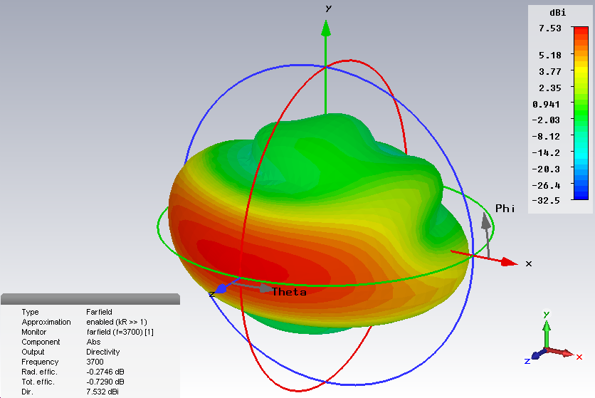
Difference to VCAD is that positive Z is further from mic.
Difference to VCAD is that positive Z is further from mic.
I have given Vituixcad a try. It's a good but overwhelming piece of software. I think Vituixcad is in SERIOUS need of a new and much more understandable manual than the current one.
Ps. In the 'Options' menu, if I try to change the 'Crossover font', the program immediately crashes. Bug?
Ps. In the 'Options' menu, if I try to change the 'Crossover font', the program immediately crashes. Bug?
Ps. In the 'Options' menu, if I try to change the 'Crossover font', the program immediately crashes. Bug?
I suppose you might have Arial font installed if program does not crash immediately when Options window opens? That is default font family which was required while first run with previous builds.
The latest built (uploaded few minutes ago) tries font family of Options window if Arial is not installed, but that workaround won't work either if .NET does not recognize installed fonts at all.
In typical case (~99.9%) no problems with XO font selection.
Last edited:
I think Vituixcad is in SERIOUS need of a new and much more understandable manual than the current one.
It's freeware so you should primarily donate or participate. Rewrite all manuals if you can. Start with Finnish, French, Polish, Spanish, Russian, Chinese, Japanese versions and finalize English and German to be understandable. Nagging and listing requirements won't help anything or anybody in this case.
I have given Vituixcad a try. It's a good but overwhelming piece of software. I think Vituixcad is in SERIOUS need of a new and much more understandable manual than the current one.
Ps. In the 'Options' menu, if I try to change the 'Crossover font', the program immediately crashes. Bug?
As someone who has written a Manual before (The Unofficial Speaker Workshop Manual V1 and V2), I can tell you that it is no small undertaking. This is a tremendous piece of software and the Manual is very good at highlighting the salient points bringing you to the point where it really only takes a little bit of experimentation to make everything clearly understandable. Kimmo has done a remarkable job of keeping up with it. If you are having problems understanding something, reach out here and Kimmo and others have been more than gracious with their time and explanations. Attacking, as you did, is neither fruitful nor does it show the appreciation that we should all have for his efforts, his knowledge, and his dedication to the DIY world.
Jay
Manual is far from perfect for sure. One issue is that some sections are not much more than feature lists while some others tell how to work; where to click and which order.
Typical user from my point of view does not even open help documents. Just send long e-mail, and my reply is just copy+paste from user manual or measurement prep. and suggestion to read documentation.
Another main group does not understand my English or forgets previous pages while reading forward. For them I have repeated instructions few times by e-mail with different words or word order or some example(s).
Individual may also require description of some numerical methods. That could duplicate length of manual without any change to simulation result assuming that user follows written recommendations/instructions - with or without knowledge how calculation works. Many basic functions and calculations are easy to test and verify against other programs or theory. Known and simplified test data is quite easy to generate with tools.
Majority probably reads and understands or is able to use the program (without manual) via experience with some other program such as LspCAD which has been "role model" for many functions and design philosophy.
Feedback is allowed of course though this freeware. I can't live with this so programming has been DIY hobby - which also supports my (minor) work with commercial speakers.
When I wrote the post I had no idea who 'kimmosto' is. The post was not explicitly written to him but merely as a general consideration, regarding the program and what I (still) consider the lack of a 'sensible' manual. How anyone can see this as an 'attack' is beyond my grasp. The rather rude answer from kimmosto, I think, shows that this matter with the manual is a rather sensitive thing.
Either way - the answer I got from kimmosto and you has not exactly increased my desire to explore vituixcad further. And no, I'm not going to write a manual, which kimmosto suggested or donate any money. Vituixcad is uninstalled and SoundEasy is on its way.
With that said, I wish everyone a good day!
^^Enjoyable moments with SoundEasy (which I also have/had though not much used). Nice that someone still supports commercial software and their authors.
P.S. You original feedback was invaluable rather than rude (as mine). Should suggest something concrete and specific or simply ask or investigate independently or select some other program if any of previous does not suit. Not just general complain of something.
P.S. You original feedback was invaluable rather than rude (as mine). Should suggest something concrete and specific or simply ask or investigate independently or select some other program if any of previous does not suit. Not just general complain of something.
Last edited:
So, I made a custom waveguide, mimicking the Buchardt s400’s. This sets the tweeter back into the enclosure by 33mm. I attempted to design it so that the depth of the waveguide put the voice coil on the tweeter drive at the same Z measurement as the voicecoil on the woofer. But, if the front of the baffle is actually the reference point, then I am -33. Or +33? The difference between -33, 0, and +33 makes quite a difference and a noticeable dip in the sound at the crossover frequency. This is the source of my issue. I really don’t know if when accounting for that waveguide, if I am -33, 0, or +33mm.
But in the end, I am really trying to set up to take real measurements instead of using theoretical specs, as I am sure that will give me the best results.

Do you mind posting more details regarding your build? I'm looking to mimic a similar setup and would appreciate more guidance on the crossover and specs of your DIY build. Thanks!
Do you mind posting more details regarding your build? I'm looking to mimic a similar setup and would appreciate more guidance on the crossover and specs of your DIY build. Thanks!
I will attempt to do so, once I have finished my project to my satisfaction. I was unhappy with my first attempt at a crossover. Following advice here, and making measurements. Actually got to go do that right now......tick tock
Rev. 2.0.24.0 (2019-09-07)
* Angle density of simulated and visualized off-axis directions is selected with Angle step [deg] list box in Options window. Available options are 5, 10, 15, 20 and 30 deg, initial 10 deg. Angle step of drivers' off-axis responses loaded in Drivers tab could be denser, fewer or equal to angle step of simulation. Measured angle step could be constant (0, 10, 20, 30, ..., 180) or variable (5, 10, 15, 20, 30, 40, 50, 60, 80, 100, 120, 150, 180). Off-axis responses of different driver types can have different angle step, constant or variable.
* Allowed Reference angles follow Angle step setting. Range of Reference angle is minimum coverage of drivers' frequency responses, or max -90...+90 deg if Half space is checked in Options window.
* Power response and directivity index are calculated within minimum coverage angle of drivers' frequency responses i.e. 0-180 deg must be measured for all drivers in Drivers tab in order to calculate Power & DI to full space.
* Added Room response overlay to Power & DI chart.
This is quite significant upgrade which would deserve new version number 2.1 and license fee too 🙂
Measured and simulated off-axis directions are finally "divorced" which enables some laziness with measurements. Typically with woofer of 3-way if off-axis responses are possible to interpolate without significant error.
Note that it's not wise move to interpolate dipole over 90 deg due to polarity swap so dipole radiators are better to measure e.g. 0, ..., 70, 80, 90, 100, 110, ..., 180 deg.
Manual is far from perfect for sure. One issue is that some sections are not much more than feature lists while some others tell how to work; where to click and which order.
I totally understand that documenation is a huge task. I wouldn't even bother with multiple languages. Just do an English version, which will be good for 99% of the users.
However, the approach to "how" the documentation should be written also needs to be considered. Kimmo likes "step by step" lists, telling the user which buttons to press, and in which sequence. This may be fine for some, but it has the problem that this approach does not convey how things work behind the curtain. For me it is much more important to to understand the physics that are implemented in the code. Wihtout this information I am flying with my eyes closed, and I have a hard time to understand the meaning and relevance of the results.
But that's just me... it's Kimmos software, it's freeware, so noone is really in a position to issue any requests. Nevertheless I get the impression that Kimmo does like the idea that people make good use of his software, without asking the same questions again and again 😀
- Home
- Design & Build
- Software Tools
- VituixCAD