I tried using APO EQ a few months ago and couldn't get it to work. I have an external 31-channel stereo equalizer that I used since it was easier and I was trying to get some speakers ready for a DIY event. I'll go back and try this again soon as it would be really useful....I have attempted to put together some documentation for useful information that may not be completely obvious to everyone using the software, such as exporting the filter transfer function to APO EQ, and using the transfer function block as an "auto-EQ" type of function. Unfortunately the response to this documentation has not been very enthusiastic, there seemed to be a lack of interest ...
As far as splitting discussions to new threads, I am in favour of this. This long single thread for VituixCAD is treated more like a chat room than a forum, and like I mentioned above it makes searching through past discussions rather difficult.
One thing to think of for a "Newbie" thread might be to limit it to passive crossovers (maybe have a separate for active, if needed). When I come to this thread, with its 4000 posts, there are a lot of posts on software updates and active filters that I'm not interested in but have to wade through to get to posts that might be helpful to me in designing passive xo.
I'd either start a thread here at DIYaudio or at HTGuide since that is where the "Official Thread" is. A few observations on that point...I don't see the HTGuide thread reference anywere on https://kimmosaunisto.net/ as the official thread, the actual thread at HTGuide does not refer to itself as the "Official Thread", it comes up quite low in a Google search for VituixCAD, and it has 586 post compared to DIYaudio's 4,000 posts. If someone is looking for help and you want it to be widely accessible to anyone other than the person asking the question, the a thread here makes quite a bit more sense to me. (Right now, as I type this, there are 78 people logged into HTGuide and 764 at DIYaudio.)

Member
Joined 2003
I suppose it depends on your goals. It's hard to make some "one instruction for all" given varying levels of background experience with acoustics, electronics, computers/software, etc. There can equally be someone else on the other side of the spectrum, only interested in active DSP with no interest in passive filters. For newbies without electrical filter background, possibly without soldering experience either, I would actually suggest that starting with the active filters, DSP or APO EQ is a better place to start. The filters are predictable regardless of speaker, more easily implemented/changed for quick audible feedback to provide correlation between the graphs and reality.One thing to think of for a "Newbie" thread might be to limit it to passive crossovers (maybe have a separate for active, if needed). When I come to this thread, with its 4000 posts, there are a lot of posts on software updates and active filters that I'm not interested in but have to wade through to get to posts that might be helpful to me in designing passive xo.
I mentioned previously, ideally VituixCAD would have it's own forum, and posts would be seperated by topic, without long convoluted threads covering all topics under the sun. Splitting the discussion to focused topics makes future search-ability much easier.I'd either start a thread here at DIYaudio or at HTGuide since that is where the "Official Thread" is. A few observations on that point...I don't see the HTGuide thread reference anywere on https://kimmosaunisto.net/ as the official thread, the actual thread at HTGuide does not refer to itself as the "Official Thread", it comes up quite low in a Google search for VituixCAD, and it has 586 post compared to DIYaudio's 4,000 posts. If someone is looking for help and you want it to be widely accessible to anyone other than the person asking the question, the a thread here makes quite a bit more sense to me. (Right now, as I type this, there are 78 people logged into HTGuide and 764 at DIYaudio.)
On the "official thread" you will find in the help file a section for "support forums", where HTGuide is the only English forum in the list, and the link there takes you directly to the VituixCAD thread. But, if we can learn one thing from past topics in this thread, is that people rarely read the help file in detial before posting questions.
I do agree on HTGuide, originally I believe this thread was the "official" support thread some time ago, Kimmo moved to HTGuide after frustrations with constant barrage of basic questions (and USB mics)from people too lazy to read the help or measurement guides, as well as disagreement on design processes that get promoted here, such as the "designing without measurement" sticky. Personally, HTGuide is only a tamer discussion location due to lack of active members. Regardless, how the software is supported is up to the developer, not any of us.
Last edited:
See user manual. htguide is linked but diyaudio is not.I don't see the HTGuide thread reference anywere on https://kimmosaunisto.net/ as the official thread, the actual thread at HTGuide does not refer to itself as the "Official Thread"
Be that as it may, tools are an embodiment of much knowledge and experience. This can help users to develop a better understanding of the topic the tool was designed to assist with.But tools are not a replacement for knowledge and experience.
2.0.92.0 (2022-11-23)
Diffraction
Diffraction
- Set origin (0,0) command added to context menu of baffle image. Ctrl + mouse click is still available.
- Baffle width and height can be adjusted with text boxes after baffle is created with New button. Movement of corners is relative to selected origin (0,0).
- Baffle width and height are updated to text boxes after corner is moved with mouse or arrow keys or text box.
- Data type of location coordinates (x, y, width, height) changed from integer to floating point to avoid rounding errors in corner positions when baffle size is adjusted after initialization.
- Actual corner count and driver count saved to baffle project file.
Facebook group created. Let's see is it just extra trash to clean some day...
https://www.facebook.com/groups/454942413386350
I may post something also to twitter with #VituixCAD as @kimmosaunisto
https://twitter.com/search?q=VituixC...ed_query&f=top
https://www.facebook.com/groups/454942413386350
I may post something also to twitter with #VituixCAD as @kimmosaunisto
https://twitter.com/search?q=VituixC...ed_query&f=top
The manual VituixCAD measurements REW mention .
"Rotation center on Z-axis while off-axis measurement sequence:
a)
b) Rotation center on Z-axis varies with stepped baffle. Drivers on each baffle level has own rotation center on Z-axis. Distance from each baffle level to microphone must be constant (1000 mm). Differences on Z-axis are entered to the simulator as Z mm of the driver,
e.g. tweeter Z=0 mm, mid-range Z=-20 mm, woofer Z=-100 mm.
If I read this, I understand that the speaker must be moved back/forward to keep the distance from the driver till the microphone the same.
If so, this isnt so easy to do in my case. I made a turntable. A big tilted floorstander can not be move back/forward to have the driver on the pivot point.
Can I keep the distance the same for all drivers by lifting the speaker so that there isn't any tilt and enter the tilt difference (triangle calculation) in the driver parameters?
The text leave some room for interpretation.
Just to be 100% sure.
Member
Joined 2003
The note in the guide that you quoted is in reference to a stepped baffle, drivers all still forward facing.
With a slanted baffle, baffle should be propped forward so drivers and baffle are perpendicular to the floor. This will simplify centre of rotation and axis angles for measuring. When placing the drivers in the crossover, physical offsets must be entered, z offset based on baffle slope and driver seperation, as well as tilt angle.
With a slanted baffle, baffle should be propped forward so drivers and baffle are perpendicular to the floor. This will simplify centre of rotation and axis angles for measuring. When placing the drivers in the crossover, physical offsets must be entered, z offset based on baffle slope and driver seperation, as well as tilt angle.
@kimmostoFacebook group created. Let's see is it just extra trash to clean some day...
https://www.facebook.com/groups/454942413386350
I may post something also to twitter with #VituixCAD as @kimmosaunisto
https://twitter.com/search?q=VituixC...ed_query&f=top
I'm amazed at the amount of time and devotion you put into this thread and the HTGuide thread. 😍
So I'm not sure why you would want to create a face book page and a twitter account, and try and monitor those as well.
It does not have language restrictions. You can write in any language (also bad language) and hope that someone would understand and reply 🙂So I'm not sure why you would want to create a face book page
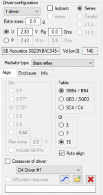
I have a question regarding the merger tool. I have two woofers wired in series in a bass reflex enclosure with one port. I have measured near field responses of one of the woofers and the port with the drivers connected in series. The far field responses I have measured with one of the woofers connected only (the other disconnected). Should I enter count as 2 for the woofer near field response or should I keep it as 1? Read somewhere back in the thread that it should be 1 for this case but that does not make sense to me

EDIT: Maybe the most intuitive is to have count of 0.5 for the port (since it is shared for two drivers) but I guess the end result is the same
EDIT: Maybe the most intuitive is to have count of 0.5 for the port (since it is shared for two drivers) but I guess the end result is the same
Last edited:
Member
Joined 2003
2 woofers, enter count of 2. count, diameter, distance all are just to pre-determine required amount of attenuation required between near and far field responses, but only works if output level, mic preamp gain is not changed between near and far field measurements. As always, use your eyes as your guide and adjust levels accordingly in the chart. In your chart, far field data has significant reflection information from 300-800Hz range, I would re-consider far field measurement and window selection before proceeding. Near field and level scaling looks okay, port output looks a couple dB too low.
Thanks, not sure what I can do with the port output level. All nearfield measurements where taken at the same output level, port diameter is correct and driver area according to spec sheet.
I have 4.9 ms of reflection free time, driver is a 3" subwoofer which seems to have some resonance issues here and there
I have 4.9 ms of reflection free time, driver is a 3" subwoofer which seems to have some resonance issues here and there
Member
Joined 2003
you can adjust it manually / visually. Reason I say it's a little low is circled in red here:Thanks, not sure what I can do with the port output level. All nearfield measurements where taken at the same output level, port diameter is correct and driver area according to spec sheet.
Neafield woofer and port response should converge as frequency approaches 0Hz. It can be tough visually if you decrease min frequency on chart <20Hz because will run into lack of signal an noise floor, but simulation response gives perfect example of what to expect:
Resonant issue is not present in nearfield response, suggesting far field reflection problem.I have 4.9 ms of reflection free time, driver is a 3" subwoofer which seems to have some resonance issues here and there
Thanks, I'll align the tails the woofer/port output.
Not sure about the cause for the smooth near field measurement and the peaks and dips in the far field, this is only seen on the woofer and not on the full range driver (same measurement setup). This is the impulse for the woofer (ignore wrong polarity):

The 400 Hz dip disappears of axis:

Exact same measurement setup was used for the full range driver which looks clean:

Not sure about the cause for the smooth near field measurement and the peaks and dips in the far field, this is only seen on the woofer and not on the full range driver (same measurement setup). This is the impulse for the woofer (ignore wrong polarity):
The 400 Hz dip disappears of axis:
Exact same measurement setup was used for the full range driver which looks clean:
I am simulating an enclosure and have a clarification to ask.
The crossover is used as shown in the diagram below.

When I don't use the "Crossover of driver" option I am able to select the "Driver Configuration" Option and add more drivers but if I select the "Crossover of driver" option than the "Driver Configuration" Option grays-out and cannot select more drivers anymore.


My question is if I add 4 drivers in crossover schematic does the App takes it as 4 drivers already added in the simulation and does not want to repeat it in the enclosure design section?
If there is some confusion in the way I am doing, pls guide the right approach to be made.
The crossover is used as shown in the diagram below.
When I don't use the "Crossover of driver" option I am able to select the "Driver Configuration" Option and add more drivers but if I select the "Crossover of driver" option than the "Driver Configuration" Option grays-out and cannot select more drivers anymore.
My question is if I add 4 drivers in crossover schematic does the App takes it as 4 drivers already added in the simulation and does not want to repeat it in the enclosure design section?
If there is some confusion in the way I am doing, pls guide the right approach to be made.
Attachments
Looks that it's my responsibility as an author to answer to difficult puzzles (though I kinda promised to stay away from diyaudio).My question is if I add 4 drivers in crossover schematic does the App takes it as 4 drivers already added in the simulation and does not want to repeat it in the enclosure design section?
If there is some confusion in the way I am doing, pls guide the right approach to be made.
Transfer function (including generator's output voltage) of ONE driver instance in XO network in the main program can be transferred to Enclosure tool. Therefore Enclosure tool prevents you to simulate more than one driver at a time when 'Crossover of driver:' is checked and driver instance is selected in Align tab. This limit does not prevent you evaluating how much you can load (power, excursion, air velocity, ...) individual driver, what volume is needed for one driver and what resonance frequency is okay with reflex system. This approach works also with passive and active filters where individual drivers in shared box volume have different components or active transfer function.
After load & excursion evaluation is ready, you can scale the system for as many drivers you like by unchecking 'Crossover...' and multiplying volume with number of drivers, increasing port area keeping Helmholz resonance constant and driver connection compatible with XO in the main program.
@kimmosto,
Hi Kimmosto, thanks for breaking your vow to answer my question.
Can I do the following?
1. Simulate transfer function with one or more driver.
2. In the XO network add required drivers and see the final results.
I reason I ask is XO Impedance, Resistance and Cross-over frequencies will get altered if I don't add multiple drivers in the final simulation.
Purpose of "Crossover of driver:" link is to TEST how much driver+enclosure system can handle voltage with certain transfer function such as Linkwitz Transform without exceeding Xmax or Pmax. Nothing else. So please do not try to DESIGN speaker so that you play with XO in the main program and driver+enclosure system in Enclosure tool at the same time so that transfer function in driver terminals and impedance response are linked between the tools. Follow recommended design procedure which can be found in user manual.Can I do the following?
I will remove this link between XO and Enclosure tool if the feature is used wrong asking too many questions on discussion forums.
Kimmo, thankyou for the powerful software. I have been following the video "Adding off-axis responses with VituixCAD Diffraction and Calculator tools"
to simulate conventional dome tweeters on a baffle. But what should I do to simulate a BMR driver where the sd affectively changes?
This is the driver I am looking at: https://www.parts-express.com/Tecto...Full-Range-Speaker-8-Ohms-297-2176?quantity=1
to simulate conventional dome tweeters on a baffle. But what should I do to simulate a BMR driver where the sd affectively changes?
This is the driver I am looking at: https://www.parts-express.com/Tecto...Full-Range-Speaker-8-Ohms-297-2176?quantity=1
- Home
- Design & Build
- Software Tools
- VituixCAD