I have narrowed down what the cause is and created a small test case to reproduce it, with project file zipped.^^.NET crash reports won't help much. I know what is missing in the code but identifying crashing control (B318TBaRGA?) is more difficult. Information where cursor/mouse was and what key was pressed etc. would be more helpful.
It happens when you delete multiple items at once (with the "are you sure" dialogue)
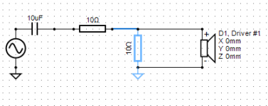
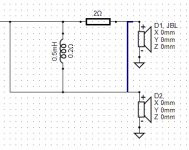
In my example, multi-select the 10 ohm shunt resistor, the earth symbol below it and the wire link between the two resistors, as shown in the image, then hit delete and confirm the dialogue - it should crash.
Try it again without deleting the wire link and it does not crash.
I was able to reproduce many more combinations of multi-selection deletions crashing. (such as drawing a box around an entire connected all pass filter)
Hopefully that helps find it!
Attachments
Last edited:
Great! It is now fixed in rev 2.0.3.3.
Very simple problem (missing null check) which was easy to find and fix with your test project.
Very simple problem (missing null check) which was easy to find and fix with your test project.
Great! It is now fixed in rev 2.0.3.3.
Very simple problem (missing null check) which was easy to find and fix with your test project.
Confirmed fixed for other cases as well. 🙂
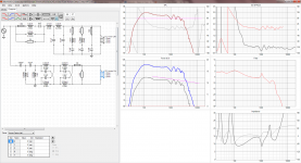
My next question is probably going to make me look stupid, but I can only seem to get Driver 1 to display on the graphs... Driver 2 acts as if muted.
If I mute Driver 1 the SPL, GD & Phase, Power & DI graphs all go blank, the impedance graph stays the same, (makes sense, because the driver is still connected) the filter response still shows the response for driver 1. (Doesn't make as much sense - how would I display the filter response for driver 2 ?)
The documentation says I should have a black curve for total SPL and individual coloured traces for each driver, but I do not have this, I only have a single brown curve for driver 1.
Have I missed something ? All drivers have frd and zma files imported and driver 2 has the correct driver file group selected. I have tried deleting and re-adding the driver. If I select the driver files for driver 2 on driver 1 it is displayed.
Screenshot attached.
Attachments
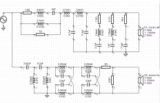
Might have found the error, but I don't understand how it happened. When I enabled node list display I see the 3.62uF capacitor for the tweeter that is supposed to be connected to the signal generator says node 12 not node 1!
How did that happen ? Also it looks like the earth point for the tweeter crossover is wrong as well - it shows node 14 on components that are supposed to be connected to the node 0 earth point ? Something not quite right with the node editor that has allowed this to happen I suppose.
Edit: If I delete the line between the signal generator and 3.62uF cap and try to redraw it starting from the middle of the line between signal generator and 1.8 ohm resistor, once the line connects it shows a dot at the top but the capacitor still lists node 12 not node 0 so there is no actual connection made in the netlist even though there is a visible connection on screen.
If I instead try to draw the same line starting at the capacitor it will not "attach" to the horizontal line from signal generator to 1.8 ohm resistor at all, so the result is inconsistent depending on which end I try to start drawing from.
Same problem at the bottom earth point - the line is displayed as connected but isn't. If I recreate it using different arrangements of line segments and a different drawing method I end up with something visually identical, but with the nodes merging properly and I now have displayed output from the driver.
The issue seems to be where a new line is started from the middle of an existing line. It looks joined complete with a dot but really isn't.
Attachments
Last edited:
I'm just guessing now but probably all wires are not connected together. Endpoint of wire must be connected either to:
- Terminal of component or
- Endpoint of another wire or
- Corner of another wire. Not in the middle of straight wire without node.
I would not use wires to combine ground. Ground symbol for each shunt is simpler and faster to draw. All pass filters are exception because output side must be separated from ground/minus terminal of generator.
General instruction is to avoid wires because it's difficult to see without single selection is everything properly connected or not.
Few examples.
An externally hosted image should be here but it was not working when we last tested it.
An externally hosted image should be here but it was not working when we last tested it.
Last edited:
Hopefully some solution can be found to emulate ways.Single source system causes some new problems compared to version 1. We can't enable/disable ways or calculate impedance response of each way etc. I've been considering multiple source system: one generator for each "way" to handle this limit. Another option would be Z/way probes or force output stage for each "way" (just like in LspCAD 6).
For example in my design because left and right driver measurements differ quite significantly I have 4 individual ways in the project with 4 driver measurements instead of two, and the left and right crossovers are custom optimised for their individual drivers instead of being identical.
In my Version 1 project I assigned ways 1 and 2 to left woofer and tweeter, and ways 3 and 4 to right woofer and tweeter. It was easy to tick an individual way, or tick pairs like 1 & 2 to look at the left speaker response and 3 & 4 for the right speaker response.
I could also tick 1 and 3 to overlay both woofers to compare how close their final response matches and 2 and 4 to compare tweeters. So the way system was ideal for my situation.
I suppose at the moment in version 2 I would need to simulate this by temporarily disconnecting the connection from the signal generator to different "ways".
Ah, makes sense, although confusing when you're not aware of it, it just seems like an error. 🙂Yes. There will be some strange phenomenon usually related to workarounds which keep equation solver running without requirement of 100% perfect network. Typical workaround is that disconnected terminal has virtual (invisible) resistor of 10 Mohm connected to node 0 i.e. ground. This is usually much more user friendly than total stop e.g. if you decide to move unused component aside temporarily.
In that case there is a bug in the line drawing routine - because it lets you start drawing a line from the middle of another line and when completed, shows a dot as if there is a connected node. But it is not really connected.I'm just guessing now but probably all wires are not connected together. Endpoint of wire must be connected either to:
- Terminal of component or
- Endpoint of another wire or
- Corner of another wire. Not in the middle of straight wire without node.
Could it not just automatically split the line into two lines segments with a node at the point that you start drawing ? Most spice simulators do this, as it is common to want to start drawing a new line from the middle of another line, as this is how you draw a circuit by hand with pen and paper.. 😉
I think that's a stylistic choice. Some people like to use individual earth symbols everywhere, I don't.I would not use wires to combine ground. Ground symbol for each shunt is simpler and faster to draw. All pass filters are exception because output side must be separated from ground/minus terminal of generator.
General instruction is to avoid wires because it's difficult to see without single selection is everything properly connected or not.
I like "busbar" earth lines and have always drawn circuits that way, and the majority of commercial circuits are (or used to be) drawn this way with individual earth symbols only to avoid unnecessary crossing of lines.
As long as there is a dot to show intersecting lines actually connect, and no bug where there is a dot shown but the lines are not really connected, it should be fine. 🙂
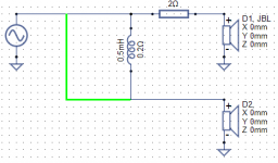
In that case there is a bug in the line drawing routine - because it lets you start drawing a line from the middle of another line and when completed, shows a dot as if there is a connected node. But it is not really connected.
Green highlighted wire visualizes valid endpoint while wiring. Dot is just a dot in the end. Problem is that dot is not yet red (will be quite soon I hope).
Could it not just automatically split the line into two lines segments with a node at the point that you start drawing?
Yes. This is already on my work list.
I don't.
Bus wires could make modification more difficult and slow. Superficial features will not be implemented very soon.
Still a bug present though - if I start from the middle of an existing line and draw a line to a valid destination like a corner, the line turns green before the final click indicating that the line will be valid, after clicking a dot is drawn at the original starting point as well to show a connection, however the line is not really joined and the actual nodes are not merged. So it looks connected but isn't.Green highlighted wire visualizes valid endpoint while wiring. Dot is just a dot in the end. Problem is that dot is not yet red (will be quite soon I hope).
If I draw the line differently, I can get a line that looks visually identical but does have properly connected nodes. For example, delete the line I wanted to draw from the middle of, draw a line from the new point back to the same place, then follow a 90 degree bend to one of the original connection points to complete that line, then draw a second line to complete the other missing piece.
Now it looks identical on the screen but it works correctly. Looking identical when drawing different ways but one works and one doesn't is a bug that will catch people out. I only figured it out after I turned on the node list display.
No extra feature is needed - by bus I just mean straight line segments, exactly as shown in my circuit.Bus wires could make modification more difficult and slow. Superficial features will not be implemented very soon.
In most circuit simulators you can freely split lines with nodes and rejoin them - some automatically remove a node when only two lines remain connected to it and add one automatically if a third line is connected to a first mid way along.
The only issue here is that depending on the method of drawing some junctions are created which look OK but don't work...
Use node number view to check connections. I am fully capable to specify what are bugs and what are just features not yet done.
I suppose at the moment in version 2 I would need to simulate this by temporarily disconnecting the connection from the signal generator to different "ways".
Yes. This is proper workaround to see impedance curve and output power (consumption) of individual ways. But it's not fast and handy for user needing quite much clicking and toggling.
About crash you found earlier. It was two days old bug related to high speed equation solver having different data type for result vector. Older slow speed solver returned zeros (not just single null) with incomplete/faulty network.
2.0.3.4 (2018-06-12)
* Wire propagation and terminal pairing improved to get red dot to terminals which are not connected to other terminal.
* Black dot removed from wire ends to avoid giving impression that wire is connected to another wire if it is not.
* Wire propagation and terminal pairing improved to get red dot to terminals which are not connected to other terminal.
* Black dot removed from wire ends to avoid giving impression that wire is connected to another wire if it is not.
^yes!! I'm super impressed with the speed at which Kimmo takes on board comments, and then brings out a new version!
I've made some progress too. I've worked out why my sims did not match the measured results. Partially stupidity, and partially my amp (made worse by the stupidity!)
My original crossover had an LPAD in it which I put before the crossover (dumb as it just causes more amp current than necessary). I had disconnected the shunt leg at some point to give the amp an easier load, with increase in HF as a tradeoff. I had recently reconnected the shunt resistor, but I soldered it onto the wrong side of the series resistor 😱 So a) it made no difference to the tweeter levels, and b) dropped the impedance seen by the amp accross the board!!
Now the second problem appears to be that my little LM3886 does not particularly like impedance's less than 3.3 ohms, and the SPL drops by around 0.5 to 0.7db when the impedance drops lower than that. So with the crossover in place (with the misplaced 22 ohm resistor), there were regions with impedance around 2.6 ohms and this results in lower output in those regions.
So, now have enough info to move forward, and do some more (hopefully better) measurements! 🙂
Tony.
Could it not just automatically split the line into two lines segments with a node at the point that...
This is now done to rev 2.0.3.5 (2018-06-13). Wire segment is splitted with a node if user clicks intermediate point while adding new wire. Wire to be added won't split even it travels via component terminal or endpoint or corner of some existing wire.
Black dots are rendered to wire junctions (with some exceptions, see changelog). Dot rendering is kinda post process and therefore dots are not visible while adding and dragging.
Could you evaluate are these features close to your expectations, please. I don't have higher requirements or plans for basic wiring anymore.
Tried out the new wire addition in the middle of a wire. It works but seems a bit finicky about whether it will attach or not. Sometimes turns green and will attach, and sometimes need to try again.
Tony.
Tony.
Sometimes turns green and will attach, and sometimes need to try again.
Green highlight is for connection to existing valid point such as component terminal or wire node. Do not mind about that because you're adding new node. Just draw new wire to intermediate point of existing wire and terminate. Dot will appear after that.
Last edited:
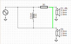
Ok just that it sometimes actually does turn green see attached 😉 I just started to add that line from the top and moved down to the corner (to see if I could reproduce) and it turned green, so I thought it was being inconsistent... edit: I guess the corner is actually a node, but doesn't show as such...
edit2: the second attachment shows sometimes it does not take. I clicked on the line and it still stayed in line drawing mode. If I move it all the way to one of the component junctions it turns green which means it is attached at the bottom (as shown in third attachment.
Tony.
edit2: the second attachment shows sometimes it does not take. I clicked on the line and it still stayed in line drawing mode. If I move it all the way to one of the component junctions it turns green which means it is attached at the bottom (as shown in third attachment.
Tony.
Attachments
Last edited:
- Home
- Design & Build
- Software Tools
- VituixCAD