Unfortunately that's not how human hearing works, since at higher frequencies our hearing places huge emphasis on the frequency response of the first arrival sound which is usually the listener axis response. This is especially true for treble >3Khz.To my experience, smooth polar response, continuous DI and carefully chosen power response tilt is far better than perfect axial response. Based on those eight speakers I have designed with 180 degree measurements both hor and ver, I am happy to sacrifice axial response to get proper polar response, because that's how speaker actually works i.e radiates in 3D space.
Smooth polar response is important but maybe not for the reason you're thinking. A smooth polar response especially near on axis is a sign of low levels of diffraction, which are important in their own right. It's also beneficial for imaging and avoids the image collapsing with small movements of the listeners head.
Any sudden changes as you go off axis should be avoided, but smooth gradual changes are usually benign unless they are extreme. I would place more emphasis on a smooth polar response than a specific polar response or a specific power response.
Again if you look at Tool and Olives research there was no specific power response found to be "best" in their research on speaker rankings, and small power response dips usually went completely unnoticed.
Only if you understand what can and cannot be heard and what variables should be optimised vs others can you design an optimal result.
Or we could look at the decades of research by people like Floyd Tool and Sean Olive who have extensively studied this using rigorously set up listening tests to evaluate what factors do and do not correlate with listener preferences and perception of sound quality.
Studies do not promise that power response could be sh*t, and their (Harman's) best products have good axial and power and other directivity features. At least I have not encouraged to make bad axial, though certain designs do not send direct (non-diffracted) axial towards listener at all.
Studies have also narrowed perspective to reality. It's very easy to agree almost anything if your reality: speaker concepts, room acoustics and listening setup are quite equal to studies or typical conservative. Conclusions are still generalizations.
Anyway, this is totally wrong thread to praise designing by axial response only or other simplistic design policies.
Where have I "praised designing by axial response only" ? Please don't misrepresent my position.Anyway, this is totally wrong thread to praise designing by axial response only or other simplistic design policies.
I made two statements:
1) The listener axis frequency response is a major correlating factor for sound quality and the power response is a minor correlating factor. This is the conclusion of Tool/Olive. You can choose to disagree with this if you like, that is your right.
This does not mean I am saying power response doesn't matter, just that it of lower importance.
2) As a result of (1) it's a mistake to try to make the power response better by making the on axis or listener axis responses simultaneously worse. For example don't put a peak in your on axis response to try to compensate for a dip in the power response.
If the power response is very poor the design of the speaker should be changed in a way that improves the power response without sacrificing axial response. Different drivers, different design altogether etc.
Aside from changing crossover slope/frequencies this is not something that can be done in the crossover as most changes that alter power response will affect axial response as well.
Anyway that's all I have to say about it so I won't keep on about it. My reply was specifically targeted to wintermute who appeared to be doing exactly what I'm advising against - making his axial response significantly less flat in an attempt to get a better looking power response.
Is there a VituixCAD formated database for tweeter FRD and ZMA files?
I have been using data I measured on two tweeters, but would like to compare results with other tweets.
I have been using data I measured on two tweeters, but would like to compare results with other tweets.
Thanks JMB and DBMandrake for your insights. Guy's sorry I didn't mean to start something here. Kimmo, would you like me to ask a mod to move this OT out to another thread (Mods participating in a thread can't moderate in that thread).
Tony.
Tony.
Where have I "praised designing by axial response only" ? Please don't misrepresent my position.
I made two statements:
1) The listener axis frequency response is a major correlating factor for sound quality and the power response is a minor correlating factor. This is the conclusion of Tool/Olive. You can choose to disagree with this if you like, that is your right.
This does not mean I am saying power response doesn't matter, just that it of lower importance.
2) As a result of (1) it's a mistake to try to make the power response better by making the on axis or listener axis responses simultaneously worse. For example don't put a peak in your on axis response to try to compensate for a dip in the power response.
If the power response is very poor the design of the speaker should be changed in a way that improves the power response without sacrificing axial response. Different drivers, different design altogether etc.
Aside from changing crossover slope/frequencies this is not something that can be done in the crossover as most changes that alter power response will affect axial response as well.
Anyway that's all I have to say about it so I won't keep on about it. My reply was specifically targeted to wintermute who appeared to be doing exactly what I'm advising against - making his axial response significantly less flat in an attempt to get a better looking power response.
Hi Kimmo and Simon,
Let me start by saying that I think that you both make good points.
One of the nice things about this hobby is that there is a subjective component that no one can argue with. Certainly above the omnidirectional frequency of a design, first arrived signals have a significant impact upon the perceived sound.
However, the power response influence has an impact on the perception of the sound, as well. Think about room influences on sound perception. If the only issue was the listening axis (or even the only main influence on the perception), room treatments and design would have little impact on the sound perception. How much the power response influences the sound may vary based upon the environment and even based upon the one listening to the sound as there are different perception pathways that have different levels of influence on the final perceived sound (sorry, I am a neuroscientist and may be getting too detailed here).
The studies done by Toole and Olive are very well done studies but are limited by population perception data. When we do research, we need to be able to control for as many variables as we can. Their data did not control on axis response and room response while looking at varying power response to my recollection; therefore one cannot deduce anything about the influence of power response from their data.
Conversely, without keeping both room response and power response constant while varying axial response, it makes it difficult to compare relative influence there, as well.
Room response signatures must also be controlled, as well, and then studied independently holding both power and axial responses constant to gain a clear understanding of it's influence level.
We must also look at Bell Curve influences. Generally we normalize based upon a chosen standard deviation range (2 is common). But what of those falling outside of that range? An example that I will provide has to do with therapeutic medication ranges. If a patient responds to a dose that is lower than the "therapeutic range", is it all in their head? No. This may well be a full physiologic response that just falls outside of a statistically chosen normal range. They might have fallen within this range had we chosen a 3 standard deviation range instead of a 2 standard deviation range.
The findings of the Toole/Olive studies are based upon reports of populations. This is a limitation and should not be taken as gospel, just trend. In research, we would call this a signal but not a finding.
Sorry, I think that my previous responses were much more succinct and likely a better response for most readers.
Jay
Where have I "praised designing by axial response only" ? Please don't misrepresent my position.
Sorry, that was not part of my reply directly to you. But if you say that axial is by far more significant than power, it's not so far that you are encouraging to leave bad power or totally skip off-axis measurements. That would not be desirable situation.
If the power response is very poor the design of the speaker should be changed in a way that improves the power response without sacrificing axial response. Different drivers, different design altogether
Agree.
who appeared to be doing exactly what I'm advising against - making his axial response significantly less flat in an attempt to get a better looking power response.
I don't agree. Overall tolerance of axial response has not changed much. Locations of dips and peaks in axial are swapped to get better power. That is exactly correct way to go if designer can't or want to change drivers anymore, and something else prevents changing slopes and x/o frequency.
--
Important in this thread is that users have visualized data to make good initial crossover, listen and study in a fairly controlled manner how much we can compromise each variable to produce good sound in target location. That information Toole & Co cannot provide for us by loose and generalized conclusions. Experienced VituixCAD users may already have some knowledge about this.
Rev 2.0.3.1 (2018-06-10):
* Crossover network calculation speed improved 15-20x by using dense matrix solver with LUP decomposition.
* Crossover network calculation speed improved 15-20x by using dense matrix solver with LUP decomposition.
Wow that's a big speed increase!
I've been having fun trying to get good correlation between my measured response and the sims. Part of the problem is I don't know the exact values of my coils, and playing around up and down a bit for the nominal values is getting closer, but I think the other issue is I still have some problems with the measurements (mainly due to the fact that they were all taken on the tweeter axis).
So I'm going to have to have another measurement day, and get full 180deg at 10 deg increments on each drivers axis individually and see how it goes then 🙂
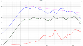
edit just realized I could do overlays in the power +di box. This is as close as I got. This is for the original crossover (that I'm now wanting to improve on). Problem is that when I adjust values to get close to the measured response, the off axis sims get less accurate, so that is why I suspect that I still have issues with the measurements (ie I'm correcting for differences, with component values, when they are probably offset issues (and the fact that the M measurements are + and - 7 deg vertical off axis). Note that the most recent measurements are better than the originals used to design the crossover, and have shown that that crossover resulted in a much less flat response that my original measurements indicated (ie I was correcting for things that weren't there!)
Tony.
I've been having fun trying to get good correlation between my measured response and the sims. Part of the problem is I don't know the exact values of my coils, and playing around up and down a bit for the nominal values is getting closer, but I think the other issue is I still have some problems with the measurements (mainly due to the fact that they were all taken on the tweeter axis).
So I'm going to have to have another measurement day, and get full 180deg at 10 deg increments on each drivers axis individually and see how it goes then 🙂
edit just realized I could do overlays in the power +di box. This is as close as I got. This is for the original crossover (that I'm now wanting to improve on). Problem is that when I adjust values to get close to the measured response, the off axis sims get less accurate, so that is why I suspect that I still have issues with the measurements (ie I'm correcting for differences, with component values, when they are probably offset issues (and the fact that the M measurements are + and - 7 deg vertical off axis). Note that the most recent measurements are better than the originals used to design the crossover, and have shown that that crossover resulted in a much less flat response that my original measurements indicated (ie I was correcting for things that weren't there!)
Tony.
Attachments
Last edited:
Limiting the upper frequency to 24 kHz is limited by the sampling frequency
Higher limit is possible to restore if performance of solver increases.
Max. internal frequency returned back to 40 kHz in rev. 2.0.3.2 (2018-06-11). It doesn't bother anymore because network calculation is 15x faster than two days ago.
Also refreshing of parameters grid is returned how it was in ver 1.1 to avoid lag in display while mouse wheeling.
Thank you Kimmo,Are you using version 1.1? That can also handle common active filter for multiple passive ways but only with tricky workaround: whole speaker should be built inside the same way by locating components to "driver nets".
Version 2 is more logical because you can split output of active section to multiple passive "ways".
Attached/linked crossover schematic would help me to understand what kind of connection (and version) you have.
If you mean that SPL graph in Enclosure tool is not changing when you modify the crossover, the reason is probably that correct driver is not selected in the main program, or Crossover of current driver is not checked.
But, I may not understand your question because merger and calculator have nothing common with that feature.
I was using version 1 and just now downloaded also version 2.
Version 1 works fine with PEQ but strange with IRR.
Version 2 does not change the responses of the enclosure tool when the crossover is activated. Also reads IRR on the schematic even when it is PEQ.
I want to insert the screenshots which are in my desktop as above but I miss something for the Insert process.
What to do?
^I suppose you mean IIR - not IRR. That is active filter technology in practice - not filter type or shape such as PEQ, LP or HP. So, I don't fully understand what you are asking.
Driver should be selected (dark blue highlight) from crossover in order to use it's transfer function in Enclosure tool. Driver should also have valid crossover network creating transfer function visible in Filter chart.
I suggest you follow instructions on my home page: download both test projects (Epe-3W_demo and Kontiainen_demo) and play with them few weeks. Study how crossover network works, how response files should be named, how component values are adjusted, how network can be modified without messing things up and how connections to other windows and tools work. Read manual as many times as needed, please. Study what is IIR, FIR and other very basic things. Google might help on this.
Rev 2.0.3.1 (2018-06-10):
* Crossover network calculation speed improved 15-20x by using dense matrix solver with LUP decomposition.
A quick question about the recommended way to install Version 1 and 2 alongside each other.
The early version 2 installer that I used a while ago now offers to install in the same directory but I chose to install in a different directory, Vituixcad2 as I prefer to keep them separated even if there aren't any filename clashes.
Given that they aren't project compatible is it best to keep their installations completely separate ?
What happens regarding sample projects and drivers etc - does Version 2 try to install these to the same locations as Version 1 or are they kept separate ?
Also it looks like despite choosing a different installation directory Version 2 has overwritten the start menu item for Version 1 ?
Ideally Vituixcad 2 should install by default in a different directory and have a different start menu icon to avoid overwriting any parts of version 1 so they can co-exist happily by default.
Is there any thought about using a different project extension for the two versions ? Could get confusing with a mix of incompatible vituixcad 1 and 2 projects with the same extension, and only one version of the program can be registered as the handler for the extension in explorer.
Last edited:
^You can install both programs into common folder below program files, e.g. "c:\Program Files (x86)\VituixCAD" in my laptop. exe files and uninstall files have different names, so they won't crash. Also shortcuts have different names; VituixCAD and VituixCAD2.
Situation was not that good in the beginning. If installation of version 2 damaged shortcuts of version 1, just reinstall 1.1.33. Everything should be okay after that.
Other compatibility:
Library blocks in Documents\VituixCAD\Library are for version 2 only. Version 1 does not need or mind that directory.
Main project files (.vxp) are not compatible 1->2 or 2->1. If you want to create the same project for both versions, you need to give different filename e.g. MyProject.vxp and MyProject_v2.vxp. Both files and auxiliary (measurement) data can be located in the same directory path.
Files compatible with both versions:
* LTSpice IV templates in Documents\VituixCAD\Templates
* Merger projects (.vxm)
* Diffraction projects (.vxb)
* Response files txt, frd, zma and so on. Exception: Merger of version 2 can create LspCAD 6 extended data format, but main program won't read it anymore.
Thanks that's great, that answers my questions. 🙂
Previously I had only installed the very first release of version 2 and tried it for a few minutes, today I've finally had time to install the latest release of version 2 and spend some time with it - I'm working to migrate my current 2 way speaker project across, part done.
So far so good, although I did get one crash when attempting to open a resource file, I think it was either frd or zma. I could not reproduce the crash a second time.
The freeform schematic design is fantastic, and the way the library blocks are combined is nice. 🙂
I don't really need to use library blocks (low pass, all pass etc) at the moment as I am only duplicating the existing design already worked out in version 1, however looking at the library blocks I'm curious to know how the program keeps track of the components that belong to a block once the user starts to directly modify individual components or even accidentally deletes or changes the connection of them ?
I assume the purge function removes all logical connections between library block components converting them to normal discrete components ?
With the signal source, it appears there can only be one onscreen, so for each "way" it's just necessary to leave room on the page to link them back to the one source ?
While constructing the circuit I noticed an odd issue - connecting the positive terminal of the driver but leaving the negative terminal floating still displays a frequency response in the graphs ? (albeit an incorrect one)
In addition, different versions have different settings because they are located in different folder below user\AppData. This is from my laptop:
c:\Users\kimmo\AppData\Local\Kimmo_Saunisto\VituixCAD.exe_Url_...\1.1.33.0\user.config
c:\Users\kimmo\AppData\Local\Kimmo_Saunisto\VituixCAD2.exe_Url_...\2.0.3.2\user.config
Running of new revision creates new folder and user.config, which has initial values copied from previous version. Removing of old folders once...twice a year might be useful.
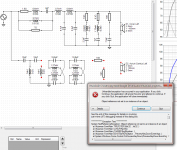
Whoops, just managed to produce a crash. See attachment for screenshot.
Below is the error text:
At the time it crashed I had just pasted two all pass filter library blocks in, then attempted to delete the earth symbol from the second one. (Since I need to connect the two in cascade, the second can't be earthed directly)
I can just manually construct the all pass filters with the values already calculated in the old design, I was just pasting the library block in to edit it to be lazy. 😀
Below is the error text:
Code:
See the end of this message for details on invoking
just-in-time (JIT) debugging instead of this dialog box.

************** Exception Text **************
System.NullReferenceException: Object reference not set to an instance of an object.
   at Vituixman.FormMain.TI0UFS7QPJ(Int32  , Int32  )
   at Vituixman.FormMain.UvKUPiRpAN()
   at Vituixman.FormMain.j7UrM8R1bq(Boolean  )
   at Vituixman.FormMain.B318TBaRGA(Object  , PreviewKeyDownEventArgs  )
   at System.Windows.Forms.Control.OnPreviewKeyDown(PreviewKeyDownEventArgs e)
   at System.Windows.Forms.Control.PreProcessControlMessageInternal(Control target, Message& msg)
   at System.Windows.Forms.Application.ThreadContext.PreTranslateMessage(MSG& msg)


************** Loaded Assemblies **************
mscorlib
    Assembly Version: 4.0.0.0
    Win32 Version: 4.7.2117.0 built by: NET47REL1LAST
    CodeBase: file:///C:/Windows/Microsoft.NET/Framework64/v4.0.30319/mscorlib.dll
----------------------------------------
VituixCAD2
    Assembly Version: 2.0.3.2
    Win32 Version: 2.0.3.2
    CodeBase: file:///C:/Program%20Files%20(x86)/VituixCAD2/VituixCAD2.exe
----------------------------------------
System.Windows.Forms
    Assembly Version: 4.0.0.0
    Win32 Version: 4.7.2117.0 built by: NET47REL1LAST
    CodeBase: file:///C:/windows/Microsoft.Net/assembly/GAC_MSIL/System.Windows.Forms/v4.0_4.0.0.0__b77a5c561934e089/System.Windows.Forms.dll
----------------------------------------
System
    Assembly Version: 4.0.0.0
    Win32 Version: 4.7.2117.0 built by: NET47REL1LAST
    CodeBase: file:///C:/windows/Microsoft.Net/assembly/GAC_MSIL/System/v4.0_4.0.0.0__b77a5c561934e089/System.dll
----------------------------------------
System.Drawing
    Assembly Version: 4.0.0.0
    Win32 Version: 4.7.2117.0 built by: NET47REL1LAST
    CodeBase: file:///C:/windows/Microsoft.Net/assembly/GAC_MSIL/System.Drawing/v4.0_4.0.0.0__b03f5f7f11d50a3a/System.Drawing.dll
----------------------------------------
System.Numerics
    Assembly Version: 4.0.0.0
    Win32 Version: 4.7.2053.0 built by: NET47REL1
    CodeBase: file:///C:/windows/Microsoft.Net/assembly/GAC_MSIL/System.Numerics/v4.0_4.0.0.0__b77a5c561934e089/System.Numerics.dll
----------------------------------------
System.Core
    Assembly Version: 4.0.0.0
    Win32 Version: 4.7.2117.0 built by: NET47REL1LAST
    CodeBase: file:///C:/windows/Microsoft.Net/assembly/GAC_MSIL/System.Core/v4.0_4.0.0.0__b77a5c561934e089/System.Core.dll
----------------------------------------
System.Configuration
    Assembly Version: 4.0.0.0
    Win32 Version: 4.7.2053.0 built by: NET47REL1
    CodeBase: file:///C:/windows/Microsoft.Net/assembly/GAC_MSIL/System.Configuration/v4.0_4.0.0.0__b03f5f7f11d50a3a/System.Configuration.dll
----------------------------------------
System.Xml
    Assembly Version: 4.0.0.0
    Win32 Version: 4.7.2117.0 built by: NET47REL1LAST
    CodeBase: file:///C:/windows/Microsoft.Net/assembly/GAC_MSIL/System.Xml/v4.0_4.0.0.0__b77a5c561934e089/System.Xml.dll
----------------------------------------
Microsoft.GeneratedCode
    Assembly Version: 1.0.0.0
    Win32 Version: 4.7.2117.0 built by: NET47REL1LAST
    CodeBase: file:///C:/windows/Microsoft.Net/assembly/GAC_MSIL/System.Xml/v4.0_4.0.0.0__b77a5c561934e089/System.Xml.dll
----------------------------------------
Accessibility
    Assembly Version: 4.0.0.0
    Win32 Version: 4.7.2053.0 built by: NET47REL1
    CodeBase: file:///C:/windows/Microsoft.Net/assembly/GAC_MSIL/Accessibility/v4.0_4.0.0.0__b03f5f7f11d50a3a/Accessibility.dll
----------------------------------------

************** JIT Debugging **************
To enable just-in-time (JIT) debugging, the .config file for this
application or computer (machine.config) must have the
jitDebugging value set in the system.windows.forms section.
The application must also be compiled with debugging
enabled.

For example:

<configuration>
    <system.windows.forms jitDebugging="true" />
</configuration>

When JIT debugging is enabled, any unhandled exception
will be sent to the JIT debugger registered on the computer
rather than be handled by this dialog box.
At the time it crashed I had just pasted two all pass filter library blocks in, then attempted to delete the earth symbol from the second one. (Since I need to connect the two in cascade, the second can't be earthed directly)
I can just manually construct the all pass filters with the values already calculated in the old design, I was just pasting the library block in to edit it to be lazy. 😀
Attachments
Last edited:
however looking at the library blocks I'm curious to know how the program keeps track of the components that belong to a block once the user starts to directly modify individual components or even accidentally deletes or changes the connection of them ?
I assume the purge function removes all logical connections between library block components converting them to normal discrete components ?
I haven't implemented any tracking from manual values back to user parameters. It would be possible with some blocks, but not always. It is best to purge the block before manual adjustments if you are sure that user parameters and math expressions are not needed anymore. Otherwise block is recalculated immediately (and manual adjustments lost) when Tune block window is opened. That could cause some disappointment I guess 🙂
With the signal source, it appears there can only be one onscreen, so for each "way" it's just necessary to leave room on the page to link them back to the one source ?
Yes.
Single source system causes some new problems compared to version 1. We can't enable/disable ways or calculate impedance response of each way etc. I've been considering multiple source system: one generator for each "way" to handle this limit. Another option would be Z/way probes or force output stage for each "way" (just like in LspCAD 6).
While constructing the circuit I noticed an odd issue - connecting the positive terminal of the driver but leaving the negative terminal floating still displays a frequency response in the graphs ? (albeit an incorrect one)
Yes. There will be some strange phenomenon usually related to workarounds which keep equation solver running without requirement of 100% perfect network. Typical workaround is that disconnected terminal has virtual (invisible) resistor of 10 Mohm connected to node 0 i.e. ground. This is usually much more user friendly than total stop e.g. if you decide to move unused component aside temporarily.
^^.NET crash reports won't help much. I know what is missing in the code but identifying crashing control (B318TBaRGA?) is more difficult. Information where cursor/mouse was and what key was pressed etc. would be more helpful.
^^.NET crash reports won't help much. I know what is missing in the code but identifying crashing control (B318TBaRGA?) is more difficult. Information where cursor/mouse was and what key was pressed etc. would be more helpful.
I clicked on the earth symbol on the right hand all pass library block then pressed the keyboard delete key to delete it.
At that instant the crash occurred. I tried to reproduce it again but as I had not saved any of the work on the second "way" I had to recreate it, and I was not able to reproduce the crash. I suspect an exact sequence of clicks or sequence of interconnections might been necessary to reproduce it.
- Home
- Design & Build
- Software Tools
- VituixCAD