Hello DaveFred,
An the last iteration above I notice a bit of a knee in both the hi-pass and filter-tweeter combi at around 1.5kHz. Just around the same frequency the Power Response seems to peak a tiny bit.
Would It help to aim for a small dip on axis @1.5 kHz in the combined response by applying a somewhat more gentle roll off in the hi pass filter? It would be interesting to see how that impacts the smoothness of the DI and Power Response.
Is this the sort of response you were describing to get a smooth power response, where one of the drivers is out of phase at the XO?
No. Phase match above XO frequency to drop power where tweeter has too wide radiation. Phase mismatch below XO frequency to increase power where cone has too narrow radiation.
But as mentioned and visualized earlier, when enclosure shape and c-c are okay, there could be phase match below and above XO frequency.
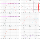
So far I dont have turn table, this is simulation with measured on axis response
and measured impedance.
I have C-C 146mm, XO 2720Hz, bafle angled back 14 degrees.
1.1" ring radiator and 7" midbas.
I think that phase belove and above XO is what Kimmo talking about.
Hope that I will be able to get off-axis in future, to check whats happen with power and DI.
and measured impedance.
I have C-C 146mm, XO 2720Hz, bafle angled back 14 degrees.
1.1" ring radiator and 7" midbas.
I think that phase belove and above XO is what Kimmo talking about.
Hope that I will be able to get off-axis in future, to check whats happen with power and DI.
Attachments
This is a bit disappointing, since I paid a bit extra for the 5Hz to 25kHz option. However, I've had mine since 2009 and is probably due for a replacement, anyway. Would love me an M30, but it is not currently within my reach. Thanks for the info.
My calibration studies happened in September 2012. Significant improvements could happen in 8 years.
Unfortunately I don't have original calibration files for ECM8000s by CSL. I had two of those. Just e-mail discussion with comments that both LF and HF of CSL were not equal to Audiomatica MIC-01 and ECM8000 by IsemCon. Those two were quite exact match at HF, but LF has uncertainties due to non-linearities in measurement signal. I don't own the truth so I just picked with statistics; experience from majority with compatible features.
I would probably try Earthworks M30. Limited spectrum of mic could be quite nasty with VCAD which likes to extrapolate up to 40 kHz.
^Your mic and calibration might be totally okay. Few calibrated references help to maintain confidence.
Member
Joined 2003
This is getting a bit off topic but I'm going to give Line Audio OM1 a try. I found a local supplier, and the price isn't crazy, still cheaper than many "calibrated" options. The OM1 isn't meant as a measurement microphone however, it does not include a calibration and the capsule is not extended from the mic body as you usually see in measurement mics. However, they advertise very linear (within 0.5dB at 1kHz and within 1dB at 20kHz) response without calibration. I have an Omnimic to compare its response to so we'll see how it compares. Worst case I can create my own calibration using the Omnimic as the calibration reference.
A question about vented enclosure
Hi Kimmo
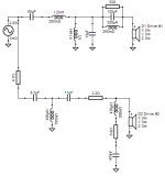
I'm making a vented box for a BOSE speaker. I use VituixCAD to simulate the box like the pic below, the thick value of front board is 1.8cm, the length of the vent is 21cm in VituixCAD2, how long should I cut the tube {(21cm+ 1.8cm)=22.8cm} vent?
Cause in VituiCAD2 help file ,no difinition about vent length, is it the inter length of the vent inside the box?
and the Diameter of the vent is 7.5CM in VituixCAD simulation, is it also the inner diameter of the tube? because I bought a tube which outer diameter is 7.5CM, and the inner diameter is 7.04CM, does this difference matter?
and sorry,I paste the pictures but they can not be displayed.

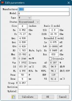
T/S parameters are here:

So I choose the vent box to simulate and I almost finish the box,except the vent and length on front board of the box.
Hi Kimmo
I'm making a vented box for a BOSE speaker. I use VituixCAD to simulate the box like the pic below, the thick value of front board is 1.8cm, the length of the vent is 21cm in VituixCAD2, how long should I cut the tube {(21cm+ 1.8cm)=22.8cm} vent?
Cause in VituiCAD2 help file ,no difinition about vent length, is it the inter length of the vent inside the box?
and the Diameter of the vent is 7.5CM in VituixCAD simulation, is it also the inner diameter of the tube? because I bought a tube which outer diameter is 7.5CM, and the inner diameter is 7.04CM, does this difference matter?
and sorry,I paste the pictures but they can not be displayed.
T/S parameters are here:
So I choose the vent box to simulate and I almost finish the box,except the vent and length on front board of the box.
Last edited:
Gentlemen,
Not to be rude, but please ask basic loudspeaker design questions on other threads on DIYAudio in the Loudspeaker section. This thread is specifically dedicated to issues that are uniquely VituixCad related.
Not to be rude, but please ask basic loudspeaker design questions on other threads on DIYAudio in the Loudspeaker section. This thread is specifically dedicated to issues that are uniquely VituixCad related.
Hi Kimmo et al,
I have a "likely" quick question that I hope one of you may be able to help with (and hope it's also ok to just briefly address this here) ...
As it is I have just built a measurement microphone based on B&K 4133 & gefell MK 221 ½ inch capsules. It is based on Herbert Rutgers microphone amplifier:
https://www.by-rutgers.nl/ME6211-PRO37R.html
although I have changed the bias resistor to effectively be 5 Gohms.
Frequency response is down to appr. 3 Hz and up to > 100 kHz (for the electronics). It also is battery driven so no phantom power needed.
Incidentally, an advantage of this design is that the microphone amplifier's effective input capacitance is quite low (appr. 1.9 pF) so that HF distortion may be reduced. Distortion is lower than -112 dB for the 2H (12 kHz sine).
Just mentioning this in case Rutger's design may be interesting to others ...
I was intending to use this measurement microphone with a measurement ADC based on AKM's AK5572, however, I just recently read in this thread about the necessary timing between the DAC output and the ADC input, and this ak5572 ADC has its own clock ... 😱 .
And since I would prefer to not have to design a new ADC/DAC combination I would much appreciate a tip on which USB sound interface people here find to work well and reliably, yet not be costly. I basically will only be using it for acoustic measurements so it should work well for this purpose only. I probably will be using either ARTA or REW softwares. And since I will not be using the phantom power it should be fine with this.
Cheers & thanks for inputs,
Jesper M
Last edited:
This is getting a bit off topic but I'm going to give Line Audio OM1 a try
good choice! each om1 is controlled against the response of an earthworks m30 and adjusted electrically for the slightly recessed mount of the mic capsule, tests done by users shows that om1 is very accurate
Member
Joined 2003
Hi Kimmo et al,
I have a "likely" quick question that I hope one of you may be able to help with (and hope it's also ok to just briefly address this here) ...
As it is I have just built a measurement microphone based on B&K 4133 & gefell MK 221 ½ inch capsules. It is based on Herbert Rutgers microphone amplifier:
https://www.by-rutgers.nl/ME6211-PRO37R.html
although I have changed the bias resistor to effectively be 5 Gohms.
Frequency response is down to appr. 3 Hz and up to > 100 kHz (for the electronics). It also is battery driven so no phantom power needed.
Incidentally, an advantage of this design is that the microphone amplifier's effective input capacitance is quite low (appr. 1.9 pF) so that HF distortion may be reduced. Distortion is lower than -112 dB for the 2H (12 kHz sine).
Just mentioning this in case Rutger's design may be interesting to others ...
I was intending to use this measurement microphone with a measurement ADC based on AKM's AK5572, however, I just recently read in this thread about the necessary timing between the DAC output and the ADC input, and this ak5572 ADC has its own clock ... 😱 .
And since I would prefer to not have to design a new ADC/DAC combination I would much appreciate a tip on which USB sound interface people here find to work well and reliably, yet not be costly. I basically will only be using it for acoustic measurements so it should work well for this purpose only. I probably will be using either ARTA or REW softwares. And since I will not be using the phantom power it should be fine with this.
Cheers & thanks for inputs,
Jesper M
There's plenty of discussion here, the ARTA thread and a few other threads on USB audio interfaces. I don't recommend Focusrite, but Steinberg UR22, Behringer UMC202HD, UMC204HD, Roland Rubix22, Motu M2, etc are all fine products for the job.
Member
Joined 2003
good choice! each om1 is controlled against the response of an earthworks m30 and adjusted electrically for the slightly recessed mount of the mic capsule, tests done by users shows that om1 is very accurate
I hope so, and we will see. You you know of any measurement accuracy comparison available online? I found some plenty of good words on it when searching, but no real data.
@Dcibel: Thanks for your feedback. I will check them out - and expect to find one that will be fine in this context. So no need to reply further to my question.
Cheers & thanks again ;-)
Jesper M
Cheers & thanks again ;-)
Jesper M
You you know of any measurement accuracy comparison available online
this is the only one i know of online, hope the pics is shown, below is direct comparsion of an om1 to an m30 in a not ideal test setup - mic tips mounted side by side touching each other hence the ripple in the response
An externally hosted image should be here but it was not working when we last tested it.
Valid is only the inner diameter of the tube! So you must enter 7.04 cm diameter in the VituixCAD, and than the tube length surely will be shorter than computed for 7.5 cm diameter - say 20 cm (for example) instead of 21 cm.I use VituixCAD to simulate the box like the pic below, the thick value of front board is 1.8cm, the length of the vent is 21cm in VituixCAD2, how long should I cut the tube {(21cm+ 1.8cm)=22.8cm} vent?
and the Diameter of the vent is 7.5CM in VituixCAD simulation, is it also the inner diameter of the tube? because I bought a tube which outer diameter is 7.5CM, and the inner diameter is 7.04CM, does this difference matter?
Length of the tube in VituixCAD is total length (say 20 cm), including board thicknes (18.2 tube + 1.8 board = 20 cm total), if you are gluing tube from inside of the box - that requires hole of 7 cm in the board.
If you drill 7.5 cm hole in the board, than you can tightly fit tube inside hole, and than the tube length should be 20 cm.
Member
Joined 2003
this is the only one i know of online, hope the pics is shown, below is direct comparsion of an om1 to an m30 in a not ideal test setup - mic tips mounted side by side touching each other hence the ripple in the response
Permission denied on that image, but no worries, I'll wait a few days and see how well it is compared to my old Omnimic as my point of reference.
Valid is only the inner diameter of the tube! So you must enter 7.04 cm diameter in the VituixCAD, and than the tube length surely will be shorter than computed for 7.5 cm diameter - say 20 cm (for example) instead of 21 cm.
Length of the tube in VituixCAD is total length (say 20 cm), including board thicknes (18.2 tube + 1.8 board = 20 cm total), if you are gluing tube from inside of the box - that requires hole of 7 cm in the board.
If you drill 7.5 cm hole in the board, than you can tightly fit tube inside hole, and than the tube length should be 20 cm.
Cool! Thank you so much.
Actually, I've made the box according to your explanation, but it sounds not good, something wrong.
Could you help me to check the picture of BOX simulation in VituixCAD2, I cannot find out what 's wrong.
Thank you very much.
Attachments
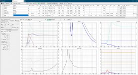
You hurried it, first comes simulation and validation, than box building.So I choose the vent box to simulate and I almost finish the box,except the vent and length on front board of the box.
Of course it sounds bad! Box volume Vb is too big, it should be only 13 or 14 litres (for one woofer), and tuning frequency Fb should be 50 Hz. Also, Rg is too high at 1 ohm, it should be the resistance of inductor in the crossover, if used - so Rg should be about 0.5 ohm, or 0.1 ohm if there is no passive crossover.Actually, I've made the box according to your explanation, but it sounds not good, something wrong.
So, you must put two woofers (serially connected) in your 28 litres box, with 7 cm tube 10.5 cm long.
Last edited:
@icbcodc
Also, 1-ohm driver is very big problem for any amplifier, even with two woofers serially connected (2-ohm total) amplifier may distort, even at low volumes. Better yet, put three serially connected woofers in the same box, sound quality will be better than with two woofers.
Also, 1-ohm driver is very big problem for any amplifier, even with two woofers serially connected (2-ohm total) amplifier may distort, even at low volumes. Better yet, put three serially connected woofers in the same box, sound quality will be better than with two woofers.
Last edited:
Cool! Thank you so much.
Actually, I've made the box according to your explanation, but it sounds not good, something wrong.
Could you help me to check the picture of BOX simulation in VituixCAD2, I cannot find out what 's wrong.
Thank you very much.
Boomy 15l, 45hz, 40mm port, 90mm long
Norm 9l, 55hz, 2x40mm ports, 121mm each
- Home
- Design & Build
- Software Tools
- VituixCAD