^^Very difficult to guess anything. Could you zip the project and attach or send by e-mail?
Project can be archived and distributed as zip file. Example of packing with batch file using 7-Zip.exe. Batch file is located and started in VituixCAD\Projectsdirectory. Parameter %1 is projectname:
@ECHO OFF
IF .%1.==.. GOTO EXIT
"%programfiles%\7-Zip\7z.exe" a -r "%1.zip" "%1\*.vx*" "%1\*.txt" "%1\*.frd" "%1\*.zma" "%1\*.pdf"
:EXIT
This happened on the last update.
When the calculator tool is opened, the last used destination directory is shown on the line. Should you click the browse symbol to change it, the window used to open up with that directory highlighted. Now it opens up at the root of the file system, which requires clicking down through umpteen layers of hierarchy to get to the desired location as opposed to up one branch and down another.
When the calculator tool is opened, the last used destination directory is shown on the line. Should you click the browse symbol to change it, the window used to open up with that directory highlighted. Now it opens up at the root of the file system, which requires clicking down through umpteen layers of hierarchy to get to the desired location as opposed to up one branch and down another.
This happened on the last update.
When the calculator tool is opened, the last used destination directory is shown on the line. Should you click the browse symbol to change it, the window used to open up with that directory highlighted. Now it opens up at the root of the file system, which requires clicking down through umpteen layers of hierarchy to get to the desired location as opposed to up one branch and down another.
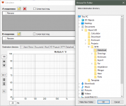
Folder browsing has not changed in a year, but temporary strange behavior is possible because root directory of browse folder dialogs was 'Desktop'. It's changed to 'MyComputer' in the latest build of 2.0.51.6 (2020-07-05) which should list full tree from 'This PC' down to previously selected folder. Should not need extra clicking of Projects folder (or full tree) to select sibling directory.
Could you test how it works in your PC.
I'm at that level. The behavior I described is with that last update. The problem is that, at least on my win10 system (which has auto update enabled) it doesn't list the full tree down to the previously selected folder. It just shows the top of the tree.
^Folder browser dialog is windows feature so folder and search options could have some effects also to .NET apps.
Open File explorer. Select File->Change folder and search options. Restore defaults in General tab, View tab and Search tab. Apply and Ok. Restart VituixCAD. Should look like this:
Open File explorer. Select File->Change folder and search options. Restore defaults in General tab, View tab and Search tab. Apply and Ok. Restart VituixCAD. Should look like this:
Attachments
Rev. 2.0.51.7 (2020-07-06). Minor improvements to help documents and names of chart traces. Updates early builds of 2.0.51.6.
I think it should be "SPL max" field in Enclosure tool (like in main program form) because now it's impossible to see whole "Total SPL Max" line on SPL graph.
..now it's impossible to see whole "Total SPL Max" line on SPL graph.
Total SPL max curve (cyan) is based on Xmax only at the moment. That increases towards infinite by frequency so any Y-axis maximum less than realistic 190 dBSPL set by user would not show whole curve in practice.
Working method is to increase Source voltage from 2.83 V up to maximum voltage available from power amplifier and monitor also power graph. Not just excursion and it's max limit which are already visible in Excursion chart. Basically Total SPL max curve in SPL chart is quite useless without power limit.
Hi. I'm a bit confused how this program response. After download frd and zma for each driver,created crossover with all connections I can't do any changes with graph at all it's simply not responding to any value changes with components.
Heeelp please 🙂
Thank you.
Heeelp please 🙂
Thank you.
^You expect that wire is cut when you drop components on it. That's not gonna happen so you have continuous shortcut from generator to both drivers and changes to component values does not have effect to responses.
Just look carefully example projects and ver 2 video and wires in your schematic and do not expect anything.
Just look carefully example projects and ver 2 video and wires in your schematic and do not expect anything.
It would be a good feature if the program behaved according to his assumptions. Some simulators work this way. Another similar feature is dropping one component on top of another replaces the older with the new one.
^Reality i.e. XO circuit connection does not work that way so assumption of breaking is kinda unrealistic. In addition, trimming could become a bit complex with complex library blocks and groups with multiple components. Doable for sure but wiring is the last phase when creating circuit so work order visible on video is not rational.
Selected component can be replaced with Ctrl+click new component. No need to drag. This is mentioned in manual.
Selected component can be replaced with Ctrl+click new component. No need to drag. This is mentioned in manual.
No problem. Understood.
Admittedly, I'm a sporadic user, and that may be the case for many other users. I'm actually wary of the shear rate of changes that the software is constantly undergoing, hoping that I don't fall too far behind.
Admittedly, I'm a sporadic user, and that may be the case for many other users. I'm actually wary of the shear rate of changes that the software is constantly undergoing, hoping that I don't fall too far behind.
^Reality i.e. XO circuit connection does not work that way so assumption of breaking is kinda unrealistic. In addition, trimming could become a bit complex with complex library blocks and groups with multiple components. Doable for sure but wiring is the last phase when creating circuit so work order visible on video is not rational.
Selected component can be replaced with Ctrl+click new component. No need to drag. This is mentioned in manual.
To be fair, the schematic editor can be a little unpredictable at times.
Whenever I physically move a component or group of components to make room for more or tidy up the layout I never quite know whether moving the components is simply going to break connections altogether (the lines going to the component stay still and dangling and components become disconnected) or whether the lines will remain connected and stretch in funny ways (usually diagonally) to remain connected.
I guess it must depend on the way the lines and components were originally created and joined together, but there is no clue from looking at the schematic visually before moving a component to know what is about to happen when you move it and whether the connection will be broken or the lines will remain connected and stretch.
Most times when I have to rearrange or move components I end up deleting and remaking all the affected lines as even if they stay connected they usually stretch in ugly ways, and what might have looked like a single line often reveals itself to be two line segments joined together with one staying still and the other stretching.
Last edited:
🙂 Ok watched 3 more times tutorial video. Add components. And again nothing changing.On tutorial video it does. Read manual. Not find this information. Anyone know good video to look at with new "2"version? Or tell when graph start to respond to adding parts?
As soon as you complete a circuit between the generator and the driver(s) the graphs will begin updating.
Graphs update in real time for every circuit and component value change, however if you don't have any path from the generator to driver(s) you will of course not get any result, just like real life. 🙂
Graphs update in real time for every circuit and component value change, however if you don't have any path from the generator to driver(s) you will of course not get any result, just like real life. 🙂
Last edited:
- Home
- Design & Build
- Software Tools
- VituixCAD