would need limits > +/-3.3m for 3 sets
Assuming about 1 m listening elevation, driver's initial Y limits from -2500 to +2500 mm allow ~3500 mm tall construction. Mirror image with floor reflection doubles that so maximum height of simulated radiator is ~7000 mm. That should be quite enough at home. Max. 5000 mm radiator is available for PA line array without floor reflection by keeping listening axis at Y=0 mm.
Again - initial Y limits are just numbers which could be +/-1 km, but what's the point because this is not for stadium PA.
I couldn't get to 7m the way I tried, the program kept repositioning my drivers. Should I use the relocate button?
I just got back to learning to use the enclosure tool crossover of driver feature and its working for me with one anomaly.
I'm considering driver's "X-file" to main program in addition to frequency and impedance responses. Excursion response would be with 1 V or 2.83 V supply voltage for one driver. That information is easy to produce for closed, vented and passive radiators by simulating with Enclosure tool or compatible, but not (so easily) for more complex systems such as resistance enclosures, horns and mixed gradient radiators.
One more graph is needed of course, but mathematically this is piece of cake assuming that radiator is ideal piston full range. Just multiplying X-response file with transfer function at driver terminals and generator's voltage / 2.83.
Should be mentioned few times that existing contrived link between main program and Enclosure tool is something I do not recommend. That was asked one persistent user, and I've been wishing that the others just forget it as a cheap workaround 🙂
I couldn't get to 7m the way I tried, the program kept repositioning my drivers. Should I use the relocate button?
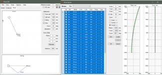
Select all drivers in Driver layout window by clicking top left corner of the grid. Set new layout parameters, click Locate button and and finally Ok button. Need to remember that listening axis is Y=0 mm and floor typically at Y=-1000 mm.
For example this setup gives 3500 mm actual radiator + 3500 mm mirror image by the floor reflection with driver Y limits +/-2500 mm.
Attachments
I'm considering driver's "X-file" to main program in addition to frequency and impedance responses. Excursion response would be with 1 V or 2.83 V supply voltage for one driver. That information is easy to produce for closed, vented and passive radiators by simulating with Enclosure tool or compatible, but not (so easily) for more complex systems such as resistance enclosures, horns and mixed gradient radiators.
One more graph is needed of course, but mathematically this is piece of cake assuming that radiator is ideal piston full range. Just multiplying X-response file with transfer function at driver terminals and generator's voltage / 2.83.
Should be mentioned few times that existing contrived link between main program and Enclosure tool is something I do not recommend. That was asked one persistent user, and I've been wishing that the others just forget it as a cheap workaround 🙂
I understand the reason for that user's persistence. Simulation should be able to tell you maxSPL and/or SPL at Xmax. That is the need however you answer it and contrivances are great if they work. I wouldn't call it cheap trick, rather a clever one. You have to model the enclosure to compute the excursion. Where else would you do it but in the enclosure tool?
You could dress it up in main program to let user right click a driver and then one of the options is to open or create an enclosure sim for it.
That is the need however you answer it and contrivances are great if they work.
Simulating single (worst case) driver with Enclosure tool and possibly finding maximum generator voltage with Power dissipation window gives the answer, but multi-step procedure is just too complex and indirect to recommend.
Link between main and Enclosure works with single drivers and maybe in all cases where Enclosure tool has compatible driver configuration (number & connection match). Basic line array theory without any simulation could be quite adequate at LF for more complex line arrays.
Attachments
Last edited:
The workaround I use is to put an amplifier block between the source symbol and the rest of the schematic. Enclosure tool graphs do follow gain changes in that block.
My philosophy is that filter gain is just filter gain. It should not play the role of adjustable voltage.
However, one more cheap trick is possible to add to avoid copying source voltage manually from Enclosure tool to generator in XO: generator voltage is copied automatically from main program to Enclosure tool when crossover link is checked and user adjusts Rg. Could be worth to force 1 driver to Driver configuration because linked transfer function is for single driver only.
^Please ignore previous two messages. Too tired to write much smart and correct. Hopefully crossover link to Enclosure tool is usable and logical with the following changes.
Rev. 2.0.50.4 (2020-05-18)
Enclosure
* When 'Crossover of driver' is checked and driver selected with combo box in Align tab:
- Number of drivers or isobaric pairs forced to one and connection switched to Series
- Generator's voltage copied from crossover in the main program to Eg
- Rg forced to 0 Ohm (included in transfer function)
- Simulated impedance response is copied back to selected driver in the main program if impedance response filename is empty i.e. not loaded from txt/zma file.
Select all drivers in Driver layout window by clicking top left corner of the grid. Set new layout parameters, click Locate button and and finally Ok button. Need to remember that listening axis is Y=0 mm and floor typically at Y=-1000 mm.
For example this setup gives 3500 mm actual radiator + 3500 mm mirror image by the floor reflection with driver Y limits +/-2500 mm.
I downloaded your latest release this AM and tried the enclosure tool. looks good!
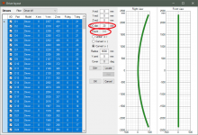
Then I tried using Locate button as you describe above. I started with 25 drivers centered on zero spanning roughly 2.2 meters. I wanted to move them up 2.2 m for a ceiling image. I highlighted the table, entered 2200 into Ymid and pressed Locate. The result is what you see below. The limit of 2500 has been enforced; the software changed my Ymid entry so the highest driver would land at 2500.
Attachments
Hi Kimmosto:
I apologize for being persistent 🙂 but in the interests of improving Vituix which I appreciate greatly:
I found additional shades of the baffle height limit. One can't use the driver offset button to relocate drivers beyond 2.5m. It also appears one can't set a driver offset Y of more than 1m.
As to how many drivers does one really need to model an array reasonably accurately, probably not many more than we already can but I can't be sure of that unless the limits are pushed back so I can see that there is no point to going further.
post 593
https://www.diyaudio.com/forums/full-range/337956-range-line-array-wall-corner-placement-60.html#post6209889
also post 591
Thanks,
Jack
^Once again 🙂 Nominal listening axis is at Y=0 mm. That's the elevation where virtual mic/ear is normally located. Speaker's origin (X,Y,Z=0,0,0 mm) has always the same elevation (Y mm) with virtual mic/ear in VituixCAD. Top of the graphs in Driver layout window is 2500 mm above mic/ear while mic/ear is located at normal/nominal listening spot.
So in your example two messages below the lowest driver is half a meter above mic/ear, and top driver is 2500 mm above mic/ear. Hard to believe that this is your design target, but of course it's possible that someone want to design 3500 mm tall speakers.
P.S. Y limits of driver component are +/-5000 mm in the latest build. That gives more room for temporary driver offset adjustments via Room tab. You can verify that you have the latest by clicking any driver. Y Min and Max should be -5000 and +5000.
You can verify that you have the latest by clicking any driver. Y Min and Max should be -5000 and +5000.
This should be checked with new project or driver because Y Min & Max are saved to project file so old projects are almost doomed to stay in smaller package.
Yes, I need to start a new project to make a ridiculously tall baffle but how else can I model an infinite line array?
Starting with an existing model has been the problem all along this morning.
Starting with an existing model has been the problem all along this morning.
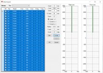
^Have you considered scale model? Here is 240 drivers with C-C=20 mm, total height ~5 m free air, ~10 m with floor reflection and ~15 m with floor+ceiling. This could be scaled e.g. 3x for C-C=60 mm => actual height ~14 m free air and 42 m with both mirror images. Not even close to infinity though.
Attachments
Tomorrow I can make a change which expands driver's min and max Y when relocated with Driver layout window.
^Have you considered scale model? Here is 240 drivers with C-C=20 mm, total height ~5 m free air, ~10 m with floor reflection and ~15 m with floor+ceiling. This could be scaled e.g. 3x for C-C=60 mm => actual height ~14 m free air and 42 m with both mirror images. Not even close to infinity though.
That is a great suggestion and I will take it unless the tomorrow's effort per the post that follows this quoted one bears fruit.
and thanks for doing this!
Hello,
this is my first post here and I may be doing this incorrectly. If so, My apologies.
I am trying to learn the Vituix program and am currently having trouble with the Merger tool. I have made measurements and converted the .pir to .frd for both far- and near-field.
In the Merger tool the near-field cone looks like this:
https://www.diyaudio.com/forums/attachment.php?attachmentid=845303&stc=1&d=1589842111
The farfield driver looks like this:
https://www.diyaudio.com/forums/attachment.php?attachmentid=845304&stc=1&d=1589842111
together they look like this:
https://www.diyaudio.com/forums/attachment.php?attachmentid=845305&stc=1&d=1589842111
That doesn't look right at all. Can anyone tell what I'm doing wrong just from this much information?
I am grateful for any and all assistance.
Attachments

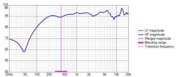
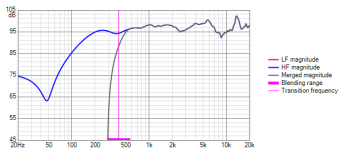
The near-field (low frequency part) should be brought up to 95 dB level with the scale/dB feature.
Now it is at -40 dB or so.
Now it is at -40 dB or so.
Tomorrow I can make a change which expands driver's min and max Y when relocated with Driver layout window.
This change is done. Summary of final built 2.0.50.4 (2020-05-19):
Enclosure
* When 'Crossover of driver' is checked and driver selected with combo box in Align tab:
- Number of drivers or isobaric pairs forced to one and connection switched to Series
- Generator's voltage copied from crossover in the main program to Eg
- Rg forced to 0 Ohm (included in transfer function)
- Simulated impedance response is copied back to selected driver in the main program if impedance response filename is empty i.e. not loaded from txt/zma file.
* Added 'Save changes to local driver database' message.
Driver layout
* Driver's XYZ limits expanded from defaults if necessary.
* Layout graphs scaled by driver locations.
That is a great suggestion and I will take it unless
Scale model mixes relation between mechanics and crossover. It's also limited to 2x due to max 40 kHz so let's forget that and try to make 1:1 model decent also for totally ridiculous theoretical studies 🙂
- Home
- Design & Build
- Software Tools
- VituixCAD