More seriously, measurement program itself is just part of measurement system, and doing own application without dedicated hardware would not solve any problem compared to existing programs such as ARTA or REW. I have CLIO (12 QC at the moment) due to dedicated controllable hardware which is calibrated. No need to play with series resistor and potentiometers of soundcard and make some annoying calibration routine after something is touched or not sure how it was. Just setup and measurement sequence with autosave, and VituixCAD processes the rest.
^I'm not smart enough. Just simple countryman between 50 and dead 🙂
***I think you are modest! 🙂
More seriously, measurement program itself is just part of measurement system, and doing own application without dedicated hardware would not solve any problem compared to existing programs such as ARTA or REW. I have CLIO (12 QC at the moment) due to dedicated controllable hardware which is calibrated. No need to play with series resistor and potentiometers of soundcard and make some annoying calibration routine after something is touched or not sure how it was. Just setup and measurement sequence with autosave, and VituixCAD processes the rest.
***I heard you!
The reason for change in polar map is that origin of the speaker i.e. listening axis changes when microphone offset is adjusted. It's usually very difficult and slow to adjust location of all driver instances in crossover to simulate just small X,Y changes in listening point. Much easiest is to change position of virtual mic/ear which kinda moves whole construction up-down and left-right from listener's point of view.
So main beam of the speaker (usually) shoots below mic/ear i.e. to negative vertical angle when mic/ear is moved up, and so on.
Keeping polar map unchanged while adjusting mic offset would require different calculation for polar map end everything else, and some horizontal line/ruler to show mic/ear position in chart. More work and probably reduced performance. Maybe more intuitive, but not in my opinion 🙂
So the polar maps are along that listening axis! When I have a speaker with a narrow vertical beam and I move the microphone and listening axis up far enough, then in the polar map that main beam is below the listening axis. That is exactly what I see and makes perfect sense now that I understand the process better.
Certainly not asking you to change that since it already works so well!
but there are a couple of things I might dare ask for:
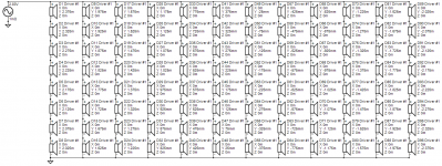
I wonder if would be possible to allow a few more drivers (<=75) and taller baffle (+/- 2.5m)? I hesitate ask because I suspect it would break things. Its already slow near the existing limits but I can tolerate that to get a few answers. Expanding those limits allows me to add sets of ground and ceiling image drivers for more accuracy. Most cases I enable reflections in the room response tab but I can't do that and get a mic offset at the same time.
I keep stubbing my toe against things tools and tab related that don't get saved/restored in the project files. I think the room response checks and entries are one such thing. File paths in the tools are another. The worst example is having an entire simulation built around a particular mic offset and coming back to the sim after some time having forgotten what that mic offset was.. These apparently come up as last used. I guess that is reasonable depending on how one works but for me what would work best is having project defaults that I could establish for all those things.
Thanks,
Jack
Thanks guys! Hopefully I can keep this software alive and add some new features in the future, though new ideas and motivation are slowly decreasing. Maybe because it's already so perfect 😀
-Kimmo
Are you offering FIR Maximum and minimum phase ? Great software and have donated.....

my email....... david@infiniteaudiovisual.co.uk
allow a few more drivers (<=75) and taller baffle (+/- 2.5m)?
Limits are just numbers in the program. We can test how long coffee break is needed after changes 🙂
I enable reflections in the room response tab but I can't do that and get a mic offset at the same time.
I'll try to fix that. Reflection calculation and mic offset are different generations having some differences in coordinate system so I have prevented simultaneous use until problems are solved.
I keep stubbing my toe against things tools and tab related that don't get saved/restored in the project files. I think the room response checks and entries are one such thing. File paths in the tools are another.
I will add key parameters in Room tab to project file. History is that mic offset was originally just hidden debugging feature, and 1st order reflections are not fundamental design parameters of typical speaker (imo) so saving to project file is just delayed until someone really needs them. Mic Y is important also for me and will be added for sure.
Tool settings and project files are independent from main project file.
Awesome!
Please just don't inch up to those limits I proposed. If experience is any guide, I will find I want to go a little higher as soon as I get there.
Please just don't inch up to those limits I proposed. If experience is any guide, I will find I want to go a little higher as soon as I get there.
As a spoiler I'm changing Microphone offset to Driver offset i.e. X,Y mm parameters change location of all driver instances in crossover. That solves reflection issue and still serves original goal to test changes in listening axis. Also adding Relocate button which moves all drivers to new positions if X,Y offset produces better result than original.
Rev. 2.0.50.3 (2020-05-16)
Main program
* Microphone offset group in Room tab renamed to Driver offset. Location of all driver instances in crossover can be changed temporarily by X,Y mm.
* Added Relocate button to Driver offset group in Room tab. Location of all driver instances in crossover are changed permanently by X,Y mm.
* Enabled reflection simulation simultaneously with driver offset.
* Parameters in Room tab saved to project file.
* Max 75 drivers can be added at once with Driver layout window.
* Initial Y Min/Max of driver component increased to -2500/+2500 mm.
* Y scale of Driver layout graphs expanded to -2500...+2500 mm.
* Drivers added with Driver layout window are located to crossover schematic on the right side of existing drivers.
--
Unfortunately driver offset is not as easy and logical as microphone offset was - especially with line arrays, but it works with reflections and enables permanent movement of drivers with Relocate button.
That is awesome; I've already used it no problems or surprises to get responses vs driver offset with reflections!
I have to admit I blew it on requested baffle height. We need 6.5m total baffle height for 75 drivers spaced 84mm for the popular TC9FD
I have to admit I blew it on requested baffle height. We need 6.5m total baffle height for 75 drivers spaced 84mm for the popular TC9FD
Are you offering FIR Maximum
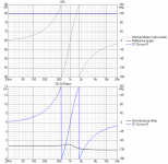
Few all-pass and phase linearisation options are available with generic active all-pass block. VCAD is able to export IR so IRL application requires FIR convolution app/plug-in. For example this is L-R48 phase linearisation.
Attachments
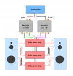
Since the MiniDSP 2x4 HD is able to process 32bit/192kHz and apparently has better sound processing compared to the older 2x4, MiniDSP for me might be back in the game, so I read through the manual and couldn't find any reference for 3 & 4 way loudspeakers. On the surface, it should be able to be used in mono and split the incoming chn to 3/4 outgoing channels.
Included a block diagram of how I intend to use it. Anyone else doing this and any known issues ?
Included a block diagram of how I intend to use it. Anyone else doing this and any known issues ?
Attachments
One of those seals is called as "Pullervo" which is "Chubby" in English, but I don't know is this the one.
The latest build of rev. 2.0.50.3 (2020-05-17)
Driver layout
* Layout parameters of existing drivers detected when window opens.
Driver layout
* Layout parameters of existing drivers detected when window opens.
Just tried to add two groups of 25 drivers one above and one below the original 25. When I checked Y in driver layout and schematic, I saw that the Y's had been changed to keep the drivers within the +/- 2500mm boundaries. Even going to schematic and changing a y one at time, the software will set anything you enter above 2500 back to 2500.
Each set of 25 spans ~2.2 meters so would need limits > +/-3.3m for 3 sets
Each set of 25 spans ~2.2 meters so would need limits > +/-3.3m for 3 sets
I just got back to learning to use the enclosure tool crossover of driver feature and its working for me with one anomaly. What made the difference was your suggestion to set it to single driver. The anomaly though is that excursion and power levels don't follow the voltage setting feature you just added to the source block. The workaround I use is to put an amplifier block between the source symbol and the rest of the schematic. Enclosure tool graphs do follow gain changes in that block.
- Home
- Design & Build
- Software Tools
- VituixCAD