Thanks for bringing this forward, I forgot to mention waveguides in the post to expand the context. There can be small source on large baffle without much baffle edge diffraction, if it is in a waveguide. The waveguide controls the sound to lower frequencies than the source alone would, and keeps bulk of it reaching the baffle edge.My 3D simulations don't agree with this specific statement (I agree with your general premise but not how you have worded it here).
https://www.diyaudio.com/community/...aker-build-abec-modelling.357792/post-6287595
I do agree with this that if the baffle is minimized the bulk of the diffraction is removed.
The amount of the effect varies, a dome tweeter than has a rocketing DI is quite different to a good waveguide that has been made to have more constant directivity as seen in the link above. The horizontal coverage pattern matters too.
However, if the waveguide was much smaller than the baffle leaving flat baffle area around the waveguide, there can be sound along the baffle and to the edge depending on the crossover frequency. Small waveguide on a tweeter like Morel CAT378 has mostly effect on the very high frequencies, but I doubt it has any control lower on the crossover region. I suspect in this case similar analogy would work nicely, wavelengths bigger than the waveguide, but smaller than the baffle would likely show some baffle edge diffraction like with direct radiators. I haven't tested it and depends on million things, but if there is any baffle edge diffraction it would locate on this bandwidth.
It is true one can support the tweeter response with the baffle, it is the baffle step and seen in the diffraction sim. Or do you mean something else? Wide baffle to support the tweeter low end response is valid method, it just comes with the trade-off of some more diffraction. And the diffraction can be cured by for slants or roundovers or perhaps a towel around the tweeter.I have, a couple of times, here is the first one
https://www.diyaudio.com/community/...aker-build-abec-modelling.357792/post-6287575
Second one here
https://www.diyaudio.com/community/...aker-build-abec-modelling.357792/post-6441116
If there is a desire to push the tweeter to lower frequencies then the baffle helps that as it changes the 2pi to 4 pi transition, this is something that Vituix does not model and in some cases the effect on the overall directivity can be significant.
I forgot to write in the post there are trade-offs for the minimized baffle as well, like having no support for tweeter low end and having multiple baffle steps on a single system, if all ways were on their own minimized baffles, adding complexity to crossover.
The VituixCAD diffraction model is pretty simple, just a baffle with edge, and doesn't apply exactly to real 3D objects. The underlying phenomenon how waves interact with each other and the physical objects around would be the same for most part, and I think there is still much generalized info in the simple VituixCAD sims that help give insight how things would work out in real speaker. This helps apply suitable band aid in a real situation. Measurements and BEM simulations give much more detail how it would work out in reality and the insight from simple sims, or just by thinking wavelengths, can help to understand what needs to be done in order to change for better, be it more support for tweeter or less diffraction interference. Depends on the objectives for any given project and situation, valuable thing here is the added knowledge.
Yes! The freestanding waveguide is kind of the weird on in the bunch showing no diffraction from bottom to top and immunity to objects close by as you demonstrate. I ment in my post that we cannot forget rest of the system, the woofer. The waveguide is on the way of the woofer, and the sound from the woofer would diffract on the waveguide. There are ways to minimize this, like beaming or waveguided woofer, but it might come again with trade-off in system DI. One could use open baffle woofer and have the waveguide on the side null for the most part. Or perhaps some other tricks. Huge multiple entry horn, but again possibly shows diffraction on the taps.The freestanding waveguide termination has a remarkable way of not being bothered by anything around it
I'm not sure if this is problem at all and goes just as an academic study over small wiggle on some graphs. Wanted to bring it out though since a freestanding waveguide is the king in this regard with by far widest bandwidth capability without issues. Lets not forget rest of the system.
Have you done BEM sim how woofer sound is affected by nearby waveguide on same baffle? or freestanding one close by? This would be very interesting to see if there is effect and is it meaningful and are there ways to try and minimize it.
Last edited:
I got this working as well few days ago, responses from ABEC to VCAD, and was about to ask what is wrong with the phase 😀 There is some weird peaks going on in the phase data. I'm gonna look into this some dayVituix doesn't natively simulate waveguides but the data from other programs or measurements can be imported and added in to an overall simulation.
For example this ABEC simulation shown in VACS can be exported as text and imported into Vituix. I made a script for renaming the files to the Vituix naming convention to automate the procedure. It's not perfect and I have never worked out why the phase is all wrong (probably my fault) but the magnitude works very well.
Yes and no. Yes it can but I would still try to keep the baffle minimal. No, in that there are two steps to the change in directivity one from the baffle dimension and one from the baffle and enclosure depth combined. This gives more low frequency directive control in reality than is predicted by simple baffle step calculations. Ignoring this extra directivity either through basic simulation or prototyping could lead to less than optimal result or not 🙂It is true one can support the tweeter response with the baffle, it is the baffle step and seen in the diffraction sim. Or do you mean something else?
More details and explanation here and in the posts below
https://www.audiosciencereview.com/...rket-requirements-gathering.27212/post-946807
I don't remember but maybe not because most of the woofer sims were half symmetry and the waveguide ones 1/4. I might be able to go back to the smaller test sims and drive the woofer if I didn't.Have you done BEM sim how woofer sound is affected by nearby waveguide on same baffle? or freestanding one close by? This would be very interesting to see if there is effect and is it meaningful and are there ways to try and minimize it.
Yep me too but not today.There is some weird peaks going on in the phase data. I'm gonna look into this some day
Interesting....I have a question that I was wondering about and this thread appeared and seems to be inline with the topic of my inquiry, so I hope you don't mind me asking here.
Looking at voicing versus room correction...in one situation you want just the drivers output and no reverb and in the latter situation you have reverb of the room....both jobs are aimed at adjusting FR. One could skip voicing for the room dominated portion of the passband and go straight to room correction. In the same light....would measuring and designing a crossover make more sense to design within the room as well, if the xover point is also within the room mode? In this way, we would take measurements in room, in position, and then design the xover using that data versus using anechoic type measurements.
Looking at voicing versus room correction...in one situation you want just the drivers output and no reverb and in the latter situation you have reverb of the room....both jobs are aimed at adjusting FR. One could skip voicing for the room dominated portion of the passband and go straight to room correction. In the same light....would measuring and designing a crossover make more sense to design within the room as well, if the xover point is also within the room mode? In this way, we would take measurements in room, in position, and then design the xover using that data versus using anechoic type measurements.
Last edited:
Camplo, think it like as practical matter. The speaker acoustic output is in 3D into the room. The speakers are positioned in the room and the listener is in the room, all 3D. You should definitely take the room and listening situation into account while designing a system, but if you measure and tweak the crossover by the in room response it applies for the current room and speaker and and listening position only. The whole crossover now includes the speaker, the room and listening position as complete system. If you move the speaker or listening position the system changes and crossover needs adjustment. You might have to adjust all parameters for the new position, which might get tedious and silly settings on the crossover like huge boost on a null.
Best thing you can do is to make the crossover for the speaker, so that the speaker works nicely anechoic, and have the room correction as "another layer" on top so that it can be adjusted for changing situation. The speaker construct doesn't change during years, keep the crossover for that, and think the room correction as adjustments to the changing environment. I think you are right thinking that only the response at listening position matters (what ever that is, dance floor or auditorium, or single seat in living room) and in that sense room correction could be part of the crossover. It is just not very practical to make and maintain.
Job of the crossover is to divide and process signal in electric domain so that the sound combines back in acoustic domain, at expected listening position. In this respect it is correct to think room correction is needed or at least could be useful in given application. The important thing is that the speaker system is designed and made so that it works in the application in the first place. This enables additional room EQ applied without too much side effects. Basically some kind of controlled directivity that is planned in the application in mind.
I know you have plan for rather small and static sweet spot. For readers, room correction by EQ is not the magic pill that fixes any system, it works mainly for one listening spot only. Move little and response might be worse than without, because the correction is applied before the acoustic 3D domain and affects speaker output to all directions. Hence, "room correction" is most effective in the acoustic domain, in the physical construct of the system.
Last edited:
Is it so also for the vertical response? I have been recently simulating a woofer-coaxial-woofer arrangement and trying to optimize the enclosure shape for smooth directivity. I can maintain nice horizontal polars, but the vertical response is much more affected by the woofers. The fact that I have two of them with symmetric vertical spacing not help either.The freestanding waveguide termination has a remarkable way of not being bothered by anything around it
https://www.diyaudio.com/community/...aker-build-abec-modelling.357792/post-6510277
The simulations showing the effect on an infinite baffle version of a waveguide and woofer are here
https://www.diyaudio.com/community/...aker-build-abec-modelling.357792/post-6492454
https://www.diyaudio.com/community/...end-other-uniq-adventures.377221/post-6879588
I believe so, I did not specifically simulate the vertical. In previous simulations of the waveguide in the baffle both the horizontal and vertical were affected by including the woofer as a boundary. In the freestanding the horizontal was virtually unaffected. As long as there is some free air around the termination it is effective in both directions. It would not be easy to make an MTM like this but it could be done.Is it so also for the vertical response?
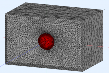
In your simulations are you simulating the woofer as a reflective boundary? This is what I did but it is not accurate as a woofer is not a totally reflective boundary exaggerating the effects, ABEC is not as comprehensive as COMSOL in these terms even though damping can be added in ABEC I would be guessing what amount use for different surfaces and it would depend on the construction of the driver and materials too.
This ^, I can't see the relevance to this thread in camplo's question though.Best thing you can do is to make the crossover for the speaker, so that the speaker works nicely anechoic, and have the room correction as "another layer" on top so that it can be adjusted for changing situation.
Room correction is a terrible name for the best use of that type of DSP function. How wide the correction can hold is very dependent on the directivity of the speakers and how the correction was made. With the right windowing and smoothing combined with relatively constant directivity the corrections can be valid over quite a large area. The "room" correction should be limited to the modal and transition regions, but an in room correction can still be used above there but it should be targeting the speaker and not the room. If the speaker was well designed there should be very little left to correct above transition.I know you have plan for rather small and static sweet spot. For readers, room correction by EQ is not the magic pill that fixes any system, it works mainly for one listening spot only. Move little and response might be worse than without, because the correction is applied before the acoustic 3D domain and affects speaker output to all directions. Hence, "room correction" is most effective in the acoustic domain, in the physical construct of the system.
Yes, I have assumed the woofer to be a hard reflective boundary. The multiphysics nature of COMSOL indeed offers a lot of possibilities for other kind of implementations... I should probably take this back to my project thread not to stray this discussion more than I have already done.I believe so, I did not specifically simulate the vertical. In previous simulations of the waveguide in the baffle both the horizontal and vertical were affected by including the woofer as a boundary. In the freestanding the horizontal was virtually unaffected. As long as there is some free air around the termination it is effective in both directions. It would not be easy to make an MTM like this but it could be done.
In your simulations are you simulating the woofer as a reflective boundary? This is what I did but it is not accurate as a woofer is not a totally reflective boundary exaggerating the effects, ABEC is not as comprehensive as COMSOL in these terms even though damping can be added in ABEC I would be guessing what amount use for different surfaces and it would depend on the construction of the driver and materials too.
Last edited:
Is this question for me? I'm not sure if I understand it or if I'm qualified to answer but here goes. Frequencies that have relatively short wavelength to the structure shape/feature size will show most effect. If you further assume the transducer size / directivity that outputs sound over the structure you are able to limit the highs outside.
The question was to all readers but I am not sure I phrased it that well. I was asking what the datum/reference response should be in order that deviations from it due to the cabinet shape are straightforward to interpret.
Now I think we can agree on a constant velocity across our perfect piston. We can also probably agree that our perfect piston has a size equal to the effective area of the driver we wish to represent. We can also probably agree that it is circular. But is it in an infinite baffle, free space, square box, spherical box,...? If we choose one then we will have a particular non-flat radiation impedance. Do we then adjust the value of the velocity with frequency so that the product with impedance is held constant and, for example, all the variations in frequency with piston size in the reference/datum show up in the variation of impedance with none in the pressure?
We essentially have two relevant acoustic quantities that vary with frequency and opting to hold one flat is not an unreasonable thing to do but it has the potential to hide things a bit. Just wondering if sharing the wiggles in some way might be more informative and easier to work with.
I would like to think that presentation of results that is something similar that in VituixCAD for example, polar maps and frequency response in general would be most familiar to folks. I'm not sure if I followed since it is very advanced question?😀
I guess almost any visual output from sims would do if there are multiple variations and some ideal to reason from. I mean, from a set of data we can probably reason and generalize what feature in a construct corresponds to what feature(s) in the output graphs as long as the data is relevant to the performance. We'd also need similar graph for "ideal" situation in order to be able to reason what features would possibly get towards it. Mabat did pretty nice job on this with the ATH script standard black and white report format showing various graphs. I think it is rather easy to compare features of waveguides to parameters that make them by looking at the reports.
Hopefully this is not too much out what you ask. Maybe others are more familiar with the question and can give proper answer 🙂
Great thread!
I played around with it a little bit trying to simulate a wide baffle like Troels PMS (I built a pair and they measure really smooth). However, I guess when a radius is entered in VCAD, it applies to all the edges? If the baffle is rounded with a large radius only on the sides, and very small top and bottom, it can't be simulated, right?
I'm also thinking how to simulate slanted (I guess that is the correct term?) when there is a wide baffle that is slightly angled to create a narrow flat baffle about the with of the drivers, and the rest is slightly angled backwards? I guess this would be somewhere in between a narrow baffle and the actual wide baffle, with some diffractions coming off all the edges? Is there some 'rule of thumb' for slanted baffles?
I also tried to see the effect of the height from the floor. It seems to me that a speaker standing on the floor should get more reinforcement in the bass, than one on 'feet'? This does not seem to be the case? Entering a distance of 5cm over the floor did not seem to make any difference to the LF. I guess only the floor bounce at listening position is calculated?
(wanted to try this since my speakers are on feet abt 5cm high, and I tried putting pillows in the gap, and thought I heard a change in the bass)
^ Look here https://heissmann-acoustics.de/en/schraege-fasen/
Yeah the VituixCAD diffraction simulator is limited with the rounding all around, no support for slants as you describe. However, you could change the baffle shape from rectangular to something else to estimate what the effect might be.
About the floor height:
The diffraction tool is basically a virtual measurement setup and it generates anechoic horizontal and vertical "measured" response to various angles. This is also the recommended procedure for real speakers and measurements. Try and minimize effect of the room in the measurements.
For this reason I suggest try the floor in the diffraction simulator as guide for you to find driver positions etc. right when you try get some sort of preliminary baffle and driver layout for a project. Leave floor out when you export the responses to the main program though, as would be the case with real speaker measurements per the VituixCAD measurement guide.
If you want to inspect effect of floor (and ceiling and front and side wall) reflection to listening position VituixCAD has the "Room" tab on the main program for this. You can input simple room (corner) model of your listening situation and see simplified first reflections and inspect the combined effect in the In-room estimate graph, what is their magnitude, bandwidth they affect etc. relative stuff, not absolute truth. More elaborate room simulations would require some other software.
Here is some thoughts that help you to get started 🙂
- Room sized bass wavelengths are dominated by the room so don't put too much attention there.
- As you find out floor bounce doesn't affect bass much since path length difference through the bounce in comparison to direct sound is pretty short as we sit close to floor and the bass is probably relatively close to floor as well. Interference starts (combfilter) when path length difference compared to wavelength gets close to half wavelength and when the difference is roughly less than 1/4wl there is only constructive interference.
- The ceiling is much farther away than floor making longer path length difference and the interference happens lower in frequency than floor reflection. However, your ceiling might have much more attenuation ( thin surface finish + lots of insulation behind) than concrete slab floor.
- In real room there would be more walls (the other side, back) and reverberation and what not, so the room model here is perhaps more for aid thinking over the stuff and reality would be quite a bit more complex.
- don't take the output literally, but take notes what bandwidths are affected etc. to help you with your design process.
- If you can freely position your speakers in your listening room, I'm not sure if there is any help with the room related info at this stage. But if the speaker needs to be close to wall, or ceiling or what ever it might provide insight for possible problems and things you could possibly exploit or should avoid in your design.
Last edited:
Thank you for the insight and link!
Seems making steep angles like 35deg next to the tweeter would be hard on a wide baffle 🙂 Maybe with a piece of MDF slapped on the wide baffle, but then again that would most likely measure completely different.
How do you go about simulating multiple drivers in the diffraction sim? I tried two drivers in the baffle, but could not make them different sizes. Is there a way place the drivers of a 3-way and move them around? I'm thinking that some diffraction effects in XO frequency range could compensate each other (small bump in tweeter response compensated by a small dip in mid response etc). Ok, it wouldn't be perfect in all directions, but maybe worth considering?
I'm thinking the same for FR for drivers, a dip in the response could maybe partially be compensated by a small hump from diffraction?
I tried loading some frd's in the diffraction sim, but can't get the to show in the graph. Could be scaling, or something else.. I can't find a way to change the dB scaling in the diffraction sim. Is it at all possible to use a frd as baseline and apply diffraction effects to that? I missed that functionality in Edge.
Re mulitway baffles, you need to do each passband individually like in the attachment. You also need the "fullspace" button checked to see the effects of the baffle on your selected frd file.
HTH,
David.

HTH,
David.
Just an FYI.....if one were to model the above as separate cabinet spaces.....VituixCad will still see all the baffles once positioned within the xover details.
Last edited:
Re mulitway baffles, you need to do each passband individually like in the attachment. You also need the "fullspace" button checked to see the effects of the baffle on your selected frd file.
Yes, David Morison is correct, we must do a baffle sim for each driver. If we want to apply the baffle sim to the measured or OEM-traced response, then we have to check the full space button and give Vituixcad a pathname to the response curve. If we are using ideal driver responses, the full space button is greyed-out.
Vituix doesn't natively simulate waveguides but the data from other programs or measurements can be imported and added in to an overall simulation.
For example this ABEC simulation shown in VACS can be exported as text and imported into Vituix. I made a script for renaming the files to the Vituix naming convention to automate the procedure. It's not perfect and I have never worked out why the phase is all wrong (probably my fault) but the magnitude works very well.
Hi Fluid, could you supply a zip file with the polar responses of an ideal tweeter in a typical waveguide? for instance, a 25 mm piston radiator in a 5 inch waveguide? We could then use this in vituixcad.
There can be no such thing as an ideal dome tweeter either on a baffle or especially in a waveguide. The shape of the dome and surround has a massive effect on the response. A pretty accurate simulation can be made that predicts the lumps and bumps if the dimensions are accurate enough.Hi Fluid, could you supply a zip file with the polar responses of an ideal tweeter in a typical waveguide? for instance, a 25 mm piston radiator in a 5 inch waveguide? We could then use this in vituixcad.
A compression driver works reasonably well as a flat disc as most manufacturers aim for that to come out from phase plug. If they choose something else that is more spherical then the simulation won't be as valid with a flat disc as source. The shape of the wavefront entering a waveguide makes a big difference to which type of curve will give the desired result.
I might be able to give you something as I have augerpro's waveguide and SB26A simulated fullspace in a minimal cabinet, but at this point the phase is still useless.
Attachments
Understood... and if phase is useless, the VituixCad simulation will not be valid. I would have guessed that you could estimate the phase based on the magnitude, using Hilbert... but honestly, I know so little about waveguide simulation I am just guessing.
I am trying to establish some simulations using hypothetical drivers, to promote my own understanding of driver size, spacing, baffle layout, baffle size, and edge treatment. I hope to share this information with others by way of this thread. My primary interest at this time is in direct radiators, but I realize that many people have an interest in waveguide technology and application.
I am grateful you are participating in this thread.
In your opinion, is it possible to create hypothetical waveguide tweeter simulation? One that would be useful, and reasonably representative of waveguide tweeters in general?
j.
- Home
- Loudspeakers
- Multi-Way
- VituixCad Simulations with Ideal Drivers