This is an outgrowth of another thread. It was suggested that we needed a new thread where people could post their VituixCad simulations to enhance the general knowledge of cabinet diffraction issues and baffle layout.
It started with AllenB making a point:
I added my thoughts:
So that is what this thread is about. It would be cool if this thread becomes a repository for interesting simulations...
j.
Note: My first two sims in post #3 and #42 have an error, which is explained in the next dozen or so posts...
It started with AllenB making a point:
Ironing a driver flat shouldn't be a problem if you choose the passband carefully, however there are many peaks and dips in measurements but many are not due to the drivers. If you EQ them all you may create problems.
I added my thoughts:
To expand on what Allen is saying: It is very enlightening to experiment with VituixCad2 using ideal driver responses, and then simulate a 2-way speaker in a box.
Ideal drivers are the "default" option when you first open VituixCad, the drivers have a perfectly flat response. The next step is to use the diffraction tool and create some baffle shape, and then simulate the horizontal and vertical responses of the ideal tweeter and ideal woofer.
The next step is to build a crossover filter using the active elements available in VituixCad, such as low pass, high pass, notch, shelf, etc. Experimenting with active elements eliminates the complexities of impedance and electrical phase, and it allows us to concentrate on just the acoustical behavior of the simulation.
We might expect that with ideal, perfectly flat drivers, it would be very simple to get a flat response... however, if we simply slapped on a basic LR2, BW3, or LR4 crossover, we would not get a satisfactory result. We will often need quite a bit of filtering to achieve a good response. Baffle step is one obvious area we will have to deal with, but there are other diffraction effects as well. There are also acoustical interactions between the woofer and tweeter depending on their spacing, and on the crossover frequency and slope.
If the goal is a flat on-axis response and a good directivity index behavior, we might need quite a bit of experimenting in VituixCad to get a good simulation. What I found is that there are some baffle shapes/layouts which are easy to work with, and getting a good result is simple... There are other baffle shapes/layouts which are difficult to work with.
If there is an interest, I can post some of the more interesting results I have found... but I don't want to clog up this thread unless there is an interest.
So that is what this thread is about. It would be cool if this thread becomes a repository for interesting simulations...
j.
Note: My first two sims in post #3 and #42 have an error, which is explained in the next dozen or so posts...
Last edited:
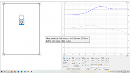
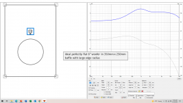
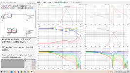
To start with, I will show a simulation I made about 6 months ago, as I was learning to use the full capability of VituixCad2. This is a simple rectangular baffle, 350mm x 250mm (approximately 14" x 10"), with a large edge radius. The drivers are a 6" woofer and a 29mm tweeter. They were positioned on the baffle as close as they can be (taking into account the mounting flanges). I did not use simulation to optimize the positioning. The driver responses in VituixCad are ideal responses, flat from 0 Hz to infinity. Since I am using active filter elements, I don't need to worry about impedance or sensitivity considerations, this is exploring and modeling the acoustical response of the drivers in a box.
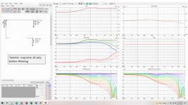
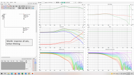
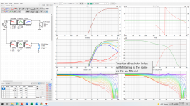
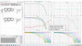
Graphics 1 and 2 show the Vituixcad diffraction tool, and how it models the woofer and tweeter responses. The horizontal and vertical responses (0 - 180 degrees) are exported, and then used in the main VituixCad crossover application. Graphics 3 and 4 show the tweeter and woofer responses of the drivers in the box... in other words, VituixCad is taking into account the diffraction at all angles from 0 to 180 degrees.
Graphic 5 shows what happens if I simplistically apply a baffle step compensation to the woofer and then slap on an LR4 crossover at 2 kHz. Since these are perfect ideal drivers, this should work out fine, right? eh, not so much. The result is not terrible, but it could definitely be improved. The response is not flat on-axis, and since we are starting with perfect drivers, a flat on-axis response should be achievable. There is a dip in the sound power curve and the ER curve, and this makes the DI and ERDI curves non-smooth.
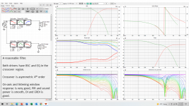
Graphic 6 shows a reasonable filter for this situation. I do not claim that it is the best that can be done, but it was the best that I could do 6 months ago 🙂.
Graphics 7 and 8 show the woofer and tweeter responses including the filtering. What is interesting is that the DI curve with filtering is the same as the DI curve of the raw driver... i.e compare graphic 7 with graphic 3... and compare graphic 8 with graphic 4.
j.
Graphics 1 and 2 show the Vituixcad diffraction tool, and how it models the woofer and tweeter responses. The horizontal and vertical responses (0 - 180 degrees) are exported, and then used in the main VituixCad crossover application. Graphics 3 and 4 show the tweeter and woofer responses of the drivers in the box... in other words, VituixCad is taking into account the diffraction at all angles from 0 to 180 degrees.
Graphic 5 shows what happens if I simplistically apply a baffle step compensation to the woofer and then slap on an LR4 crossover at 2 kHz. Since these are perfect ideal drivers, this should work out fine, right? eh, not so much. The result is not terrible, but it could definitely be improved. The response is not flat on-axis, and since we are starting with perfect drivers, a flat on-axis response should be achievable. There is a dip in the sound power curve and the ER curve, and this makes the DI and ERDI curves non-smooth.
Graphic 6 shows a reasonable filter for this situation. I do not claim that it is the best that can be done, but it was the best that I could do 6 months ago 🙂.
Graphics 7 and 8 show the woofer and tweeter responses including the filtering. What is interesting is that the DI curve with filtering is the same as the DI curve of the raw driver... i.e compare graphic 7 with graphic 3... and compare graphic 8 with graphic 4.
j.
Attachments
Thanks Jim. Very instructive.
What this highlights, to me, is that good speaker simulation and design is incredibly iterative and laborious and we have just come out of the dark ages.
Until a time that a simulator uses a GPU or AI accelerator; getting the ideal outputs from the input takes a lot fo time and dedication, and a bit of chance and circumstance. (Non Ideal drivers and non-ideal baffle shapes and drivers positions)
I think there will be correlation to shape for the tweeter. But not for the filters, at least not for DI index. Or a normalized polar map probably.
In other words: make a better baffle for the tweeter and the DI will improve.
In other words: make a better baffle for the tweeter and the DI will improve.
^^ tktran303 start teaching your own brain AI 😀 think wavelengths and most phenomena are easy to think over and connect the dots. Wavelength connects the sound to the physical objects, the transducer, the baffle, the whole construct and the room.
^ wesayo, exacto, and utilize waveguide, all tricks you have for smoothest DI. Directivity is physical property of the construct for the most part (crossover regions depend on the crossover as well, in combination with c-c distance), and thus not change if you do something in electrical domain like tweak the crossover filters. It is the driver sizes, their position in relation to each other and the structure. Diffraction related interference is one of the easiest detected property of the construct but the DI as whole depends on the physical thing you have put together.
^ wesayo, exacto, and utilize waveguide, all tricks you have for smoothest DI. Directivity is physical property of the construct for the most part (crossover regions depend on the crossover as well, in combination with c-c distance), and thus not change if you do something in electrical domain like tweak the crossover filters. It is the driver sizes, their position in relation to each other and the structure. Diffraction related interference is one of the easiest detected property of the construct but the DI as whole depends on the physical thing you have put together.
What are the reference conditions to impose with frequency when you wish to see the effects of the speaker shape? I am working on this at the moment for a set of BEM simulations.
In answer to Turk182, I would consider the above baffle as one which is difficult. I did other sims where I moved the woofer and tweeter around a bit, but it did not make much improvement. The problem with this baffle layout is that it forces the designer to use a crossover of about 2.2 - 2.5 kHz. The woofer in particular has a slow roll-off, it is down by -10 dB at 3k, and a mere -18 dB at 4k. It limits my choice of woofer to those which are exceptionally well behaved at high frequency. My usual preference with a 6" driver would be to have a crossover in the 1.5k to 1.8k range... and be down by about -20 dB at 3k.
An easy to work with baffle would be one which will work for a variety of crossover frequencies.
Yes, very true. The only way I have found to optimize a baffle shape and layout is to (1) make a guess as to shape, and driver position, (2) simulate all the driver responses, and capture them, (3) import them into the main driver response page, (4) attempt to make a crossover filter. If you want to change the position of the drivers, or the width / height of the baffle, you start back at step (1)... I do not yet have an intuitive feel for how the driver diffraction responses will interact.
I have found that the location of the "diffraction hump". When crossing from a mid to a tweeter, the size and location of this hump is important. If the crossover is within the hump region, it will be very difficult to achieve both a good on-axis and good power response… in other words, a smooth DI. A wider baffle causes the hump to be lower in frequency.

An easy to work with baffle would be one which will work for a variety of crossover frequencies.
What this highlights, to me, is that good speaker simulation and design is incredibly iterative and laborious and we have just come out of the dark ages.
Yes, very true. The only way I have found to optimize a baffle shape and layout is to (1) make a guess as to shape, and driver position, (2) simulate all the driver responses, and capture them, (3) import them into the main driver response page, (4) attempt to make a crossover filter. If you want to change the position of the drivers, or the width / height of the baffle, you start back at step (1)... I do not yet have an intuitive feel for how the driver diffraction responses will interact.
I have found that the location of the "diffraction hump". When crossing from a mid to a tweeter, the size and location of this hump is important. If the crossover is within the hump region, it will be very difficult to achieve both a good on-axis and good power response… in other words, a smooth DI. A wider baffle causes the hump to be lower in frequency.
Here is my favorite insight and experiment / demonstration with VituixCAD diffraction tool I've post many times in various threads 🙂 Relation of transducer size to the baffle and how the diffraction is affected and what kind of round overs help.
Basically the observation is as follows: To have least amount of diffraction interference in a loudspeaker response, for practical size speakers, one should minimize flat baffle around any driver. Minimizing baffle means baffle should not have too much flat around any transducer. If there are round overs or slants they should start immediately beside the driver frame, for most effect.
Here is some text to support the claim, before attachments.
Basically, baffle edge diffraction happens on frequencies that are sufficiently short in comparison to the baffle size. Long wavelengths just don't "see" the baffle and go around it, this is the baffle step. Wavelengths sufficiently short in comparison to baffle size will diffract at the baffle edge. Diffraction creates secondary sound source at the baffle edge (all around) which combines with the direct sound at the listening spot creating interference pattern, peak(s) and dip(s) on axis and the inverse somewhere off-axis. Now, any transducer will start beaming on wavelengths that are roughly shorter than the transducer size. This means that when there is transducer on a baffle there is less and less sound going to the baffle edge as frequency goes up. This leaves us a bandwidth of frequencies that diffract at the baffle edge and causes interference pattern easily seen. The problematic bandwidth low end depends on the baffle size and the high end on the transducer size. To minimize the bandwidth where diffraction (interference) happens we need to bring the baffle size to transducer size and that is all we can do because we need the transducer anyway. A minimized baffle.
If anyone remembers Olson papers which demonstrates diffraction properties of various enclosures might remember a sphere diffracts the least. This works here with baffle edge round overs. For round overs we cannot have minimal baffle (enclosure), the baffle has to extend some from the driver rim in order to fit the round over (or slant)! But as we start to widen the baffle in order to put our round over the diffracting frequency bandwidth extends lower in frequency and kind of escapes the rounding. When the round over radius approaches and goes beyond the driver diameter the baffle starts to resemble a sphere and the diffraction almost goes away. The sphere needs to be substantial in comparison to driver size to fully mitigate diffraction. Basically, we cannot get rid of diffraction completely but we can address it one way or another that is suitable for the application at hand and within limits of budget for example.
Here lays the nugget for speaker builders: there is no need for round overs or slants if you just keep the baffle minimized. No round overs are necessary for pretty good diffraction performance, there is the main hump but not much interference after that! However, any round overs help any baffle if you can fabricate them but the effect is not very much in comparison to just using minimal baffle with no round overs at all. Most of the time we cannot make minimal baffle for each transducer, because there needs to be multiple drivers on same baffle that is sized according to the largest one! Or the inside dimensions of a box behind the baffle need to be something that demands bigger baffle than the driver. Anyway, food for thought for the designers 🙂
First attachment is VituixCAD demonstration, a GIF that shows 8" ideal driver on minimal baffle and what happens as round over is introduced to the baffle. Watch how the baffle step gets lower in frequency as round overs get bigger (all frames are with no flat baffle around the driver, round over starts immediately side of the driver) and almost nothing happens to the main peak until the round overs approach the driver diameter. Some minor diffraction interference is seen above the peak around 1kHz when there is no round overs, just minimized baffle area, pretty nice for no extra labor at all! 1" round overs cure this minor ripple but do nothing to the main peak, basically on a 8" driver effect of 1" round over is very miniscule on frequencies where an 8" driver is used.

I have no idea if difference on any of these frames in the GIF is audible or not on finalized system with crossovers and other drivers in place, probably not too much difference. Biggest difference would be to wide baffle without round overs, where the diffraction ripple goes wild pretty quick when the baffle edge gets further away from a transducer, in relation to the transducer size!
8" driver on ~12" baffle is not too bad, dip appears after the hump, worse than on minimal baffle:

But 1" tweeter on ~8" baffle has pretty nasty diffraction, as the baffle size to the transducer size is big, the edges are relatively far away from the transducer:

The big peak seen in the response around 1kHz, above baffle step, is not a problem most of the time as is. It shows on DI for example, but rather easy to live with and most speakers have it anyway, possibly strategically positioned crossover in mind as Hifijim mentions. Unless big spheres or perhaps dipole / cardioid variety where the power is cancelled with the baffle step and relationship between the hump and on axis response is rather constant = constant DI, but such systems have their own intricacies.
Here is another GIF, same demo for 3" driver to demonstrate the phenomenon is relative and applicable to tweeters and any sized woofers as well:

For 1" tweeter 1" round over with minimal baffle is pretty effective, almost sphere!:

Problem is when the 1" driver is on 8" baffle due to big woofer on same baffle. Then 1" round over helps but some diffraction remains since the baffle supports tweeter much lower in frequency all the way to the crossover and the round overs would need to be closer to the woofer size to be effective, basically start right at the tweeter edge, no flat baffle for least diffraction interference. It is all relative to wavelength, baffle size and transducer size:

Dimensions for the demos are from Faital pro 8pr155 and 3fe25 but any drivers you can get hold on would show similar results. It takes few seconds to try this and see the effects. Project attached to get anyone started with their own experiments.
These are simplified demos and don't include effect of the whole box or nearby boundaries or don't claim what is audible and what is not, or what is easy to build and what is not. Main thing is to get insight how diffraction is related to physical objects through wavelength, the relationship between sound and physical world!
edit. Hifijim's previous post mentions "the diffraction hump" and how it affects to DI on a real system, and might make passive crossover and overall system response hard to achieve. I'd like to think the hump itself is not audible, just makes a hard crossover perhaps forcing to push the hump lower in frequency by widening the baffle, which in turn would begin to introduce more diffraction interference as demonstrated above. Perhaps we have a demonstration for the effects of the hump to practical systems with crossovers at some point 🙂
Basically the observation is as follows: To have least amount of diffraction interference in a loudspeaker response, for practical size speakers, one should minimize flat baffle around any driver. Minimizing baffle means baffle should not have too much flat around any transducer. If there are round overs or slants they should start immediately beside the driver frame, for most effect.
Here is some text to support the claim, before attachments.
Basically, baffle edge diffraction happens on frequencies that are sufficiently short in comparison to the baffle size. Long wavelengths just don't "see" the baffle and go around it, this is the baffle step. Wavelengths sufficiently short in comparison to baffle size will diffract at the baffle edge. Diffraction creates secondary sound source at the baffle edge (all around) which combines with the direct sound at the listening spot creating interference pattern, peak(s) and dip(s) on axis and the inverse somewhere off-axis. Now, any transducer will start beaming on wavelengths that are roughly shorter than the transducer size. This means that when there is transducer on a baffle there is less and less sound going to the baffle edge as frequency goes up. This leaves us a bandwidth of frequencies that diffract at the baffle edge and causes interference pattern easily seen. The problematic bandwidth low end depends on the baffle size and the high end on the transducer size. To minimize the bandwidth where diffraction (interference) happens we need to bring the baffle size to transducer size and that is all we can do because we need the transducer anyway. A minimized baffle.
If anyone remembers Olson papers which demonstrates diffraction properties of various enclosures might remember a sphere diffracts the least. This works here with baffle edge round overs. For round overs we cannot have minimal baffle (enclosure), the baffle has to extend some from the driver rim in order to fit the round over (or slant)! But as we start to widen the baffle in order to put our round over the diffracting frequency bandwidth extends lower in frequency and kind of escapes the rounding. When the round over radius approaches and goes beyond the driver diameter the baffle starts to resemble a sphere and the diffraction almost goes away. The sphere needs to be substantial in comparison to driver size to fully mitigate diffraction. Basically, we cannot get rid of diffraction completely but we can address it one way or another that is suitable for the application at hand and within limits of budget for example.
Here lays the nugget for speaker builders: there is no need for round overs or slants if you just keep the baffle minimized. No round overs are necessary for pretty good diffraction performance, there is the main hump but not much interference after that! However, any round overs help any baffle if you can fabricate them but the effect is not very much in comparison to just using minimal baffle with no round overs at all. Most of the time we cannot make minimal baffle for each transducer, because there needs to be multiple drivers on same baffle that is sized according to the largest one! Or the inside dimensions of a box behind the baffle need to be something that demands bigger baffle than the driver. Anyway, food for thought for the designers 🙂
First attachment is VituixCAD demonstration, a GIF that shows 8" ideal driver on minimal baffle and what happens as round over is introduced to the baffle. Watch how the baffle step gets lower in frequency as round overs get bigger (all frames are with no flat baffle around the driver, round over starts immediately side of the driver) and almost nothing happens to the main peak until the round overs approach the driver diameter. Some minor diffraction interference is seen above the peak around 1kHz when there is no round overs, just minimized baffle area, pretty nice for no extra labor at all! 1" round overs cure this minor ripple but do nothing to the main peak, basically on a 8" driver effect of 1" round over is very miniscule on frequencies where an 8" driver is used.
I have no idea if difference on any of these frames in the GIF is audible or not on finalized system with crossovers and other drivers in place, probably not too much difference. Biggest difference would be to wide baffle without round overs, where the diffraction ripple goes wild pretty quick when the baffle edge gets further away from a transducer, in relation to the transducer size!
8" driver on ~12" baffle is not too bad, dip appears after the hump, worse than on minimal baffle:
But 1" tweeter on ~8" baffle has pretty nasty diffraction, as the baffle size to the transducer size is big, the edges are relatively far away from the transducer:
The big peak seen in the response around 1kHz, above baffle step, is not a problem most of the time as is. It shows on DI for example, but rather easy to live with and most speakers have it anyway, possibly strategically positioned crossover in mind as Hifijim mentions. Unless big spheres or perhaps dipole / cardioid variety where the power is cancelled with the baffle step and relationship between the hump and on axis response is rather constant = constant DI, but such systems have their own intricacies.
Here is another GIF, same demo for 3" driver to demonstrate the phenomenon is relative and applicable to tweeters and any sized woofers as well:
For 1" tweeter 1" round over with minimal baffle is pretty effective, almost sphere!:
Problem is when the 1" driver is on 8" baffle due to big woofer on same baffle. Then 1" round over helps but some diffraction remains since the baffle supports tweeter much lower in frequency all the way to the crossover and the round overs would need to be closer to the woofer size to be effective, basically start right at the tweeter edge, no flat baffle for least diffraction interference. It is all relative to wavelength, baffle size and transducer size:
Dimensions for the demos are from Faital pro 8pr155 and 3fe25 but any drivers you can get hold on would show similar results. It takes few seconds to try this and see the effects. Project attached to get anyone started with their own experiments.
These are simplified demos and don't include effect of the whole box or nearby boundaries or don't claim what is audible and what is not, or what is easy to build and what is not. Main thing is to get insight how diffraction is related to physical objects through wavelength, the relationship between sound and physical world!
edit. Hifijim's previous post mentions "the diffraction hump" and how it affects to DI on a real system, and might make passive crossover and overall system response hard to achieve. I'd like to think the hump itself is not audible, just makes a hard crossover perhaps forcing to push the hump lower in frequency by widening the baffle, which in turn would begin to introduce more diffraction interference as demonstrated above. Perhaps we have a demonstration for the effects of the hump to practical systems with crossovers at some point 🙂
Attachments
Last edited:

Is this question for me? I'm not sure if I understand it or if I'm qualified to answer but here goes. Frequencies that have relatively short wavelength to the structure shape/feature size will show most effect. If you further assume the transducer size / directivity that outputs sound over the structure you are able to limit the highs outside.What are the reference conditions to impose with frequency when you wish to see the effects of the speaker shape? I am working on this at the moment for a set of BEM simulations.
From all kinds of experiments with real stuff and simulations past few years I'd say the usual bandwidth roughly 500-3500Hz region, wavelengths that fit your lap and are about the size of typical loudspeaker, are affected by almost all problems I've come across and would assume any structure related problems would be visible here as well 🙂 Cone resonances, reflex port resonance, modes inside enclosure, enclosure wall resonances, at least one crossover point, floor/ceiling first reflections that don't average out, transducers from 15" to 3", typical baffle widths and baffle edge diffraction issues, what have you, all land here on the same bandwidth and are sometimes hard to inspect in isolation. For this reason I'd put the BEM effort here on this bandwidth.
Last edited:
Quick thought on the diffraction hump: to get it lower means to get it lower in relation to crossover frequency. But, in order not to introduce more diffraction interference by widening the baffle and bring the hump down we can move the crossover frequency up. This means the woofer has already narrow response at crossover frequency, which dictates waveguide for the tweeter in order to not have directivity mismatch and get nice smooth DI. No biggie, have a waveguide! And good quality woofer with no issues playing high up. Or maybe a sphere?
Reasoning from the above, direct radiating speaker with flat baffle can't escape diffraction issues without introducing other issues (DI) that affect sound in listening position on a typical living room. In this respect a waveguide is quite natural way to go if one wants to push system "acoustic performance" in living room application. For near field listening, or other applications where there is less importance with off-axis sound, DI/power response might not matter too much. Also, one might choose between step/issue in the DI and some diffraction, maybe the other is more important than the other, maybe they are not too important issues for given application.
Here is some food for thought: When goal is to get very good sound performance from DIY system one should push all compromises in the system out from audio to cost and size and perhaps non important audio aspects. Choosing between diffraction and DI issues feels a no no situation for that philosophy. Does any system that features compromise between two no good options qualify as very good?🙂 Conversely, a rough one: if one is searching very good sound for living room then one should skip all speakers with direct radiating tweeters. Especially those that don't show any effort towards reduced diffraction and DI issues like having big woofer to a small tweeter.
Thanks starting the thread Hifijim! Lots of insight available from such ideal driver experiments without going into specifics of any particular speaker system or project or set of drivers. Even some philosophical speaker design stuff can be reasoned quite nicely!🙂
edit. I'm assuming living room situation benefits greatly from uniform sound on and off-axis, where issues in DI would mean somewhat less than optimal sound quality at listening position. All the variations might be miniscule, but at the end of the day even small issues add up.
Last edited:
The challenge the the hump presents to us is that it very real in the on-axis response, but it starts to disappear beyond 30 degrees, and by 60 degrees it is pretty much gone. So if you EQ the hump out of the on-axis response, you have now created a dip in the off-axis response... which probably means a dip in the room response, power response, and ER curve.
Tmuikku - your sims are interesting. I think we need to be cautious in drawing big conclusions from the sims of drivers centered in square baffles. It is well known that a driver centered in a square baffle is almost a worst case scenario. For instance, here is your 8" baffle with 1" tweeter sim, but with the tweeter moved up a bit. If I moved it horizontally, I could get it even smoother.

Very interesting discussion. Thanks !
j.
Tmuikku - your sims are interesting. I think we need to be cautious in drawing big conclusions from the sims of drivers centered in square baffles. It is well known that a driver centered in a square baffle is almost a worst case scenario. For instance, here is your 8" baffle with 1" tweeter sim, but with the tweeter moved up a bit. If I moved it horizontally, I could get it even smoother.
Very interesting discussion. Thanks !
j.
^ If you export the data to main program you can inspect diffraction to various angles. It is true that by offsetting the transducer in relation to the baffle shifts the diffraction interference around in 3D and can smooth it out considerably, especially to some particular direction, the design axis. There might be some "optimal" position for tweeter on a large baffle, that reduces problems towards listening window and possibly towards first reflections for example, while still allowing easy crossover what have you. Lots of stuff to experiment on. At the end, none of this is necessary by just minimizing the interference. More importantly all this is quite easy to experiment with VituixCAD and ideal drivers! If there is no such configuration where diffraction issues can be "redirected" to be good for both on and (important) off-axis, then minimization is the way to go. Minimization would always be good thing, but perhaps not necessary. I don't know what is enough, or what is bad amount of diffraction. All I'm doing is trying to get rid of all issues if I possibly can.
If you want to remove the hump, either do the sphere thing, or experiment with dipole and cardioid setups 😉 The hump is still there, even worse, but relationship between power and on axis is now smooth, constant DI can be EQ:d.
And as such, if going for greatest sound of them all philosophy choose dipole or cardioid over closed box if possible in the given application. Besides, open baffle folks seem to crossover below the hump! why we stretch in the closed box world above it to reach a crossover point? Because people strive for less ways for some reason, 2-way boxes are popular, fullrangers. Make 4-way speaker and crossover below the hump, like dipole people but keep it omni, no problemo 🙂 Many ways to approach things, sound in living room or in some other application. Mr. Linkwitz went with the open baffle, dipoles.
Attachments
Last edited:
Edit time over 😀 Was editing the whole thing for better wording. Anyway, main thing was these two attachments:


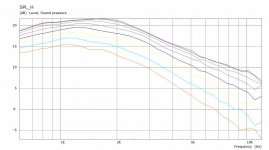
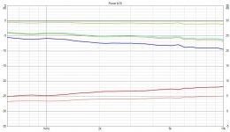
I tried to put the tweeter in a position that shows least humps and dips on the diffraction tool graph and then exported the response to main program:
While it is much better than middle of the baffle, the effect is still seen around the 1-3kHz and to get rid of it massive round overs would be required. Conversely, small round overs won't have meaningful difference.
At the end, minimizing the interference would be reasonable thing to do what ever options there is for given project. Worst thing would be to leave diffraction completely ignored never considering it at all. While no one gets injured if there is diffraction, some one who wants very good sound could not afford to overlook it I think. This is linear distortion what mr. Geddes talks about for example https://www.diyaudio.com/community/threads/geddes-on-distortion-perception.121253/.
Anyway, all this is quite easy to experiment with VituixCAD to give better chance for good sound emerge in any project!
Last edited:
Next you'll show us what a waveguide can do for the tweeter? 🙂
With a smooth transition to the baffle hopefully.
With a smooth transition to the baffle hopefully.
Why do you need a baffle for? 😀
The freestanding specimen in ATH thread are almost the best diffraction vice what I've seen, and I think fluid has done some sims with waveguid on a baffle and corresponding roundovers on the cabinet that come close the freestanding ones. Freestanding waveguide seems to be the way to go if one wants to really have least diffraction on a tweeter. Issues arise when one integrates the next way to the system, a woofer. The woofer is probably quite close to the waveguide freestanging or not and would diffract with its own structure and on the waveguide. It is all related to wavelengths and physical size of objects. In the crossover region we have two objects, transducers at least and possibly additional structure, playing on same wavelength. They could be coincident, but still there would be some issues I presume. MEH, coaxial, what have you, would all diffract at least some. Even if crossover region was nice and optimized there would still be short and long wavelengths playing on same physical structure so it is perhaps merely shifting problems to higher or lower in frequency. This would be good thing if frequency makes them less audible by hearing system. I've got no idea.
Dipole has great nulls toward the siblings, other drivers in same system. Best rejection to diffraction that I can think of. Easiest to build as well, just use enough naked drivers on some minimal structure and crossover below the drivers diffracting with their own structure. But, I think open baffle systems require some space around, between the speaker and front wall at least. While closed box speakers could benefit some space as well, at least my living room has not enough of it I think. It is also costly system, most probably multiple big woofers, multichannel DSP and amplification. While compromises are pushed from audio to cost and complexity promises a good audio quality I haven't investigated yet if there is something to exploit in dipoles for close wall positioning. Probably not, infinite baffle stuff perhaps but that is not suitable for me either so the application rules out these two promising systems for me I think. They might fit others perfectly though!
So, all in all this is just some food for thought, the diffraction stuff. Thinking with wavelengths 😉
Last edited:
My 3D simulations don't agree with this specific statement (I agree with your general premise but not how you have worded it here).Here lays the nugget for speaker builders: there is no need for round overs or slants if you just keep the baffle minimized.
https://www.diyaudio.com/community/...aker-build-abec-modelling.357792/post-6287595
I do agree with this that if the baffle is minimized the bulk of the diffraction is removed.No round overs are necessary for pretty good diffraction performance, there is the main hump but not much interference after that!
The amount of the effect varies, a dome tweeter than has a rocketing DI is quite different to a good waveguide that has been made to have more constant directivity as seen in the link above. The horizontal coverage pattern matters too.However, any round overs help any baffle if you can fabricate them but the effect is not very much in comparison to just using minimal baffle with no round overs at all.
I have, a couple of times, here is the first oneI think fluid has done some sims with waveguid on a baffle and corresponding roundovers on the cabinet that come close the freestanding ones. Freestanding waveguide seems to be the way to go if one wants to really have least diffraction on a tweeter. Issues arise when one integrates the next way to the system, a woofer.
https://www.diyaudio.com/community/...aker-build-abec-modelling.357792/post-6287575
Second one here
https://www.diyaudio.com/community/...aker-build-abec-modelling.357792/post-6441116
If there is a desire to push the tweeter to lower frequencies then the baffle helps that as it changes the 2pi to 4 pi transition, this is something that Vituix does not model and in some cases the effect on the overall directivity can be significant.
The woofer is probably quite close to the waveguide freestanging or not and would diffract with its own structure and on the waveguide. It is all related to wavelengths and physical size of objects. In the crossover region we have two objects, transducers at least and possibly additional structure, playing on same wavelength.
The freestanding waveguide termination has a remarkable way of not being bothered by anything around it
https://www.diyaudio.com/community/...aker-build-abec-modelling.357792/post-6510277
The simulations showing the effect on an infinite baffle version of a waveguide and woofer are here
https://www.diyaudio.com/community/...aker-build-abec-modelling.357792/post-6492454
I tried to put the tweeter in a position that shows least humps and dips on the diffraction tool graph and then exported the response to main program:
While it is much better than middle of the baffle, the effect is still seen around the 1-3kHz and to get rid of it massive round overs would be required. Conversely, small round overs won't have meaningful difference.
I do not see much effect from 1 - 3 kHz. By optimally placing the tweeter, you have reduced the diffraction variation to about 1 dB. That is very good for a non-radiused edge.
However, if you take your sim to the next step, and place a 5 or 6 inch driver on that baffle (taking into account the tweeter flange which is likely about 100 mm), you may find it challenging to come up with a good crossover filter... or maybe not... I have learned that it is very difficult to tell in advance which baffle configuration will be successful... you have to go through the effort of simulating the crossover.
In my post #13 I ignored the size of the tweeter flange. This is an "impossible" configuration because any reasonably sized tweeter flange would over-hang the 25 mm radius along the top, which would mean the top edge would have a much smaller radius in the area closest to the tweeter. I should have checked this before posting.
Tmuikku's post #15 is a legitimate simulation because he is using an edge radius of 0, so the tweeter flange would just fit on the baffle.
So far, much of the discussion has been focused the tweeter response. But the real difficulty comes from how the mid driver and tweeter diffraction responses interact.
Regarding waveguides: yes it is of course true that a good waveguide will control the directivity of the tweeter. But VituixCad does not simulate waveguide responses at this time. VituixCad simulates direct radiator responses. And the subject of this thread is VituixCad simulations. So I do not know where waveguides fit into this discussion... ??
Great discussion !
Vituix doesn't natively simulate waveguides but the data from other programs or measurements can be imported and added in to an overall simulation.Regarding waveguides: yes it is of course true that a good waveguide will control the directivity of the tweeter. But VituixCad does not simulate waveguide responses at this time. VituixCad simulates direct radiator responses. And the subject of this thread is VituixCad simulations.
For example this ABEC simulation shown in VACS can be exported as text and imported into Vituix. I made a script for renaming the files to the Vituix naming convention to automate the procedure. It's not perfect and I have never worked out why the phase is all wrong (probably my fault) but the magnitude works very well.
Attachments
- Home
- Loudspeakers
- Multi-Way
- VituixCad Simulations with Ideal Drivers