
Will add SIT µ-chart from Sony. It says that lower digit grades will have higher µ.
Well, at the expense of the higher drain output impedance Rd. (µ=Gm×Rd)

Some of the members here may want to investigate SIT program of the German
semis manufacturer Ditratherm (in the '75). They were made and marked with V###.
Sansui had to switch to this supplier (after NEC) with V132, V133 outputs.
TO-39 cases were, presumably, V214, V215. There were also V#### numbers,
maybe mosfets... I have noticed their mid-70s catalog in one Berlin National
library (with a membership fee...)
DITRATHERM, 1962, Elektronische Bauelemente Türk & Co KG,
8300 Landshut/Bayern, Ludmillastraße 23/25, Bundesrepublik Deutschland
Another recent addition to the SIT heritage was made by Hitachi: DPAK (Lovoltech
type) case with automotive applications in mind: ⇒
⇒ http://www.hitachi.co.jp/New/cnews/030722a.html -July 22, 2003
Recently, Silicon Carbide semiconductors have come out, so SIT (V-FET) is back again.
It seems that there is. It seems that it is 1/100 of the conventional ON resistance, which
makes it more efficient. It is also used in Prius DC-DC inverters. (2010/02/18)
Hitachi Research Laboratories (Director: Yasushi Fukunaga) has recently developed
a SIT that uses a single crystal SiC substrate.
The developed SIT has a specific Ron of 1/60 or less compared to the case of using
Si, and the loss is extremely small, so it is possible to realize miniaturization and high
efficiency of the device increase. In the future, it can be applied to power electronics
equipment such as electric vehicles, household electric appliances, and power supplies.
Transistors are used in power electronics equipment to convert alternating current and
direct current and to change voltage. At this time, heat is generated by the resistance of
the transistor, so a cooling mechanism is required and the current value is also limited.
For this reason, studies have been conducted to reduce the Ron of the transistor, but Si
is approaching the theoretical limit, and it is difficult to further reduce the loss.
Against this background, we focused on SiC, which has excellent physical properties, as
a new material to replace Si, and developed an ultra-low-loss SiC-SIT with characteristics
that exceed the theoretical limits of Si, using the following technology.
Low on-resistance by adopting a completely vertical structure with a linear current flow
path.High withstand voltage by adopting a source / gate overlapping structure that makes
it easy to apply miniaturization technology.
As a result, a withstand voltage of 2,000V, a current of 5A, and a specific on-resistance
of 15mΩ・cm² have been achieved.
The characteristics obtained this time are among the best in the world. In the future, we
aim to install it in power electronics equipment while further reducing the specific Ron.
With the widespread use of equipment with SiC elements, power conversion efficiency
will improve by almost 3%. Assuming the full-scale diffusion forecast for 2020, it is
possible to significantly save energy equivalent to seven power plants with an output of
1 million kW. At the same time, CO2 emissions are expected to be reduced by more than
10 million tons in Japan alone.
This research is a project of the Ministry of Economy, Trade and Industry, "Research
on the development of ultra-low loss power element technology", commissioned by the
New Energy and Industrial Technology Development Organization (NEDO) through the
New Energy and Industrial Technology Development Association (FED).
contact information:
Research Management Unit, Planning Office, Hitachi Research Laboratory , Hitachi, Ltd.
[Responsible: Nemoto]
7-1-1 , Omika-cho, Hitachi City, Ibaraki Prefecture 319-1292
TEL: 0294-52-5111 (Representative)
Well, Renesas doesn't list any SIT, and I didn't check the Hitachi site. Maybe someone with
the proper connections will investigate the Prius rumor(?), there was at least 4 generations
of this electronic module, but Youtube videos talk only about IGBT and MOSFET inside...
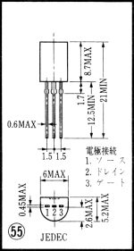
Also, there was rumor in Japan that Shindengen made UN01 as a SIT (TO-39 case) in the
mid '70s...

Well, at the expense of the higher drain output impedance Rd. (µ=Gm×Rd)
Some of the members here may want to investigate SIT program of the German
semis manufacturer Ditratherm (in the '75). They were made and marked with V###.
Sansui had to switch to this supplier (after NEC) with V132, V133 outputs.
TO-39 cases were, presumably, V214, V215. There were also V#### numbers,
maybe mosfets... I have noticed their mid-70s catalog in one Berlin National
library (with a membership fee...)
DITRATHERM, 1962, Elektronische Bauelemente Türk & Co KG,
8300 Landshut/Bayern, Ludmillastraße 23/25, Bundesrepublik Deutschland
Another recent addition to the SIT heritage was made by Hitachi: DPAK (Lovoltech
type) case with automotive applications in mind: ⇒
⇒ http://www.hitachi.co.jp/New/cnews/030722a.html -July 22, 2003
Recently, Silicon Carbide semiconductors have come out, so SIT (V-FET) is back again.
It seems that there is. It seems that it is 1/100 of the conventional ON resistance, which
makes it more efficient. It is also used in Prius DC-DC inverters. (2010/02/18)
Hitachi Research Laboratories (Director: Yasushi Fukunaga) has recently developed
a SIT that uses a single crystal SiC substrate.
The developed SIT has a specific Ron of 1/60 or less compared to the case of using
Si, and the loss is extremely small, so it is possible to realize miniaturization and high
efficiency of the device increase. In the future, it can be applied to power electronics
equipment such as electric vehicles, household electric appliances, and power supplies.
Transistors are used in power electronics equipment to convert alternating current and
direct current and to change voltage. At this time, heat is generated by the resistance of
the transistor, so a cooling mechanism is required and the current value is also limited.
For this reason, studies have been conducted to reduce the Ron of the transistor, but Si
is approaching the theoretical limit, and it is difficult to further reduce the loss.
Against this background, we focused on SiC, which has excellent physical properties, as
a new material to replace Si, and developed an ultra-low-loss SiC-SIT with characteristics
that exceed the theoretical limits of Si, using the following technology.
Low on-resistance by adopting a completely vertical structure with a linear current flow
path.High withstand voltage by adopting a source / gate overlapping structure that makes
it easy to apply miniaturization technology.
As a result, a withstand voltage of 2,000V, a current of 5A, and a specific on-resistance
of 15mΩ・cm² have been achieved.
The characteristics obtained this time are among the best in the world. In the future, we
aim to install it in power electronics equipment while further reducing the specific Ron.
With the widespread use of equipment with SiC elements, power conversion efficiency
will improve by almost 3%. Assuming the full-scale diffusion forecast for 2020, it is
possible to significantly save energy equivalent to seven power plants with an output of
1 million kW. At the same time, CO2 emissions are expected to be reduced by more than
10 million tons in Japan alone.
This research is a project of the Ministry of Economy, Trade and Industry, "Research
on the development of ultra-low loss power element technology", commissioned by the
New Energy and Industrial Technology Development Organization (NEDO) through the
New Energy and Industrial Technology Development Association (FED).
contact information:
Research Management Unit, Planning Office, Hitachi Research Laboratory , Hitachi, Ltd.
[Responsible: Nemoto]
7-1-1 , Omika-cho, Hitachi City, Ibaraki Prefecture 319-1292
TEL: 0294-52-5111 (Representative)
Well, Renesas doesn't list any SIT, and I didn't check the Hitachi site. Maybe someone with
the proper connections will investigate the Prius rumor(?), there was at least 4 generations
of this electronic module, but Youtube videos talk only about IGBT and MOSFET inside...
Also, there was rumor in Japan that Shindengen made UN01 as a SIT (TO-39 case) in the
mid '70s...


2SJ18/2SK60 ranking
Sony has been extremely shy in providing more elaborate details on their VFETs beyond the standard properties, let alone about the exact details behind their ranking system. However, the TA-8650 service manual provides a table with a hidden clue to their ranking system, as attached.
A/B are the DC gate voltages Vg, with Vds at 60V.
At the given Vg values, the VFETs are of course on, hence (slightly) above the pinch-off voltage.
Which makes me wonder if the second ranking number (3,4, etc.) simply means a factor of 2.5V for the Vp
Hence, the pinch-off voltage of rank 53 being 7.5V, etc.
It would make sense...
The above voltages should be reduced by around 0.1V and considered as Vgs voltages at Vds=60V and Id=177mA. This can be calculated from the circuit working parameters (rail voltage, bias current, voltage drop on the source resistor).
One rank 'bracket' is indeed 2.5V but it does not directly connect with the pinch-off voltage, which is actually quite difficult to define for a VFET because at some point the Vds will be enough for Id to rise (even at close to Vgs breakdown voltage!).
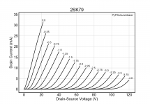
Revised Datasheet of 2SK79.

SPICE Model of 2SK79 small signal SIT
SPICE Model of 2SK79 small signal SIT
*--------------------------------------------------
*2SK79
*GENERATED BY SIT MODELER @ AUDIOHOBBY.COM
*MODEL RANGE: 100V, .01A
*--------------------------------------------------
.SUBCKT 2SK79 D G S ; Drain Gate Source
+ PARAMS: MU=33.15 X=3.97 K=0.0023 N=.096 VCT=.62 RG=2MEG
*--------------------------------------------------
B1 D S I=K*PWR(URAMP((V(G,S)+VCT)+(N*LN(V(D,S))+(V(D,S)/MU))),X)
FOR MULTISIM COMMENT OUT ABOVE LINE () AND UNCOMMENT NEXT LINE
*B1 D S I=K*PWR(MAX((V(G,S)+VCT)+(N*LN(V(D,S))+(V(D,S)/MU)),0),X)
R1 G S {RG}
CGS G S 0P
CGD G D 0P
CDS G S 0P
.ENDS 2SK79
*--------------------------------------------------
*----------------------------------------------------------------------------------
- Created on 06/29/2020 09:20 using paint_kit.jar 3.1
- www.dmitrynizh.com/tubeparams_image.htm
- Plate Curves image file:
- Data source link:
.SUBCKT 2SK79_1 1 2 3 ; Plate Grid Cathode
- PARAMS: CCG=3P CGP=15P CCP=1.9P RGI=600
- MU=30.24 KG1=45 KP=106 KVB=337.5 VCT=0.0085 EX=1.54
*----------------------------------------------------------------------------------
- Vp_MAX=93 Ip_MAX=10 Vg_step=0.2 Vg_start=0 Vg_count=10
- Rp=2720 Vg_ac=35.48 P_max=0.5625 Vg_qui=-0.9 Vp_qui=20.25
- X_MIN=163 Y_MIN=164 X_SIZE=1080 Y_SIZE=582 FSZ_X=1936 FSZ_Y=1056 XYGrid=true
- showLoadLine=y showIp=y isDHT=n isPP=n isAsymPP=n showDissipLimit=y
- showIg1=y gridLevel2=n isInputSnapped=y
- XYProjections=n harmonicPlot=y dissipPlot=n
E1 7 0 VALUE={V(1,3)/KP*log10(1+EXP(KP*(1/MU+(VCT+V(2,3))/SQRT(KVB+V(1,3)*V(1,3)))))}
RE1 7 0 1G ; TO AVOID FLOATING NODES
G1 1 3 VALUE={(PWR(V(7),EX)+PWRS(V(7),EX))/KG1}
RCP 1 3 1G ; TO AVOID FLOATING NODES
C1 2 3 {CCG} ; CATHODE-GRID
C2 2 1 {CGP} ; GRID=PLATE
C3 1 3 {CCP} ; CATHODE-PLATE
D3 5 3 DX ; POSITIVE GRID CURRENT
R1 2 5 {RGI} ; POSITIVE GRID CURRENT
.MODEL DX D(IS=1N RS=1 CJO=10PF TT=1N)
.ENDS
Attachments
*--------------------------------------------------
*2SK79
*GENERATED BY SIT MODELER @ AUDIOHOBBY.COM
*MODEL RANGE: 100V, .01A
*--------------------------------------------------
.SUBCKT 2SK79 D G S ; Drain Gate Source
+ PARAMS: MU=33.15 X=3.97 K=0.0023 N=.096 VCT=.62 RG=2MEG
*--------------------------------------------------
B1 D S I=K*PWR(URAMP((V(G,S)+VCT)+(N*LN(V(D,S))+(V(D,S)/MU))),X)
*FOR MULTISIM COMMENT OUT ABOVE LINE () AND UNCOMMENT NEXT LINE
*B1 D S I=K*PWR(MAX((V(G,S)+VCT)+(N*LN(V(D,S))+(V(D,S)/MU)),0),X)
R1 G S {RG}
CGS G S 0P
CGD G D 0P
CDS G S 0P
.ENDS 2SK79
*--------------------------------------------------
Note correction to line 10: * added.
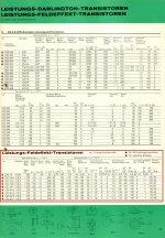
Finally got around to this ==> the 1962 catalogue is too old to be of any use as that's way too early for VFETs, but I managed to find their 1978/79 catalogue which should be juuust the right vintage, unfortunately, it doesn't list any V### parts, only the well-known Sony VFETs. Which I consider a bit... suspicious. Could it be that Ditratherm's V### parts were just house-numbered Sony VFETs...? 🤔Some of the members here may want to investigate SIT program of the German
semis manufacturer Ditratherm (in the '75). They were made and marked with V###.
Sansui had to switch to this supplier (after NEC) with V132, V133 outputs.
TO-39 cases were, presumably, V214, V215. There were also V#### numbers,
maybe mosfets... I have noticed their mid-70s catalog in one Berlin National
library (with a membership fee...)
DITRATHERM, 1962, Elektronische Bauelemente Türk & Co KG,
8300 Landshut/Bayern, Ludmillastraße 23/25, Bundesrepublik Deutschland
Attachments

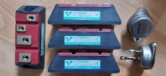
I looked into this too ==> couldn't find any commercially available SITs made by Hitachi, but speaking of Prius: Toyota, or - to be precise - Toyoda Automatic Loom Works [the parent (?) company of Toyota] does (did?) manufacture a range of SITs, e.g. TSM001, TSM002, TSM003, TSM504 or TSM506, and while the Tokin SITs were (supposedly) made to power elevators, the Toyoda parts were used in forklifts, hence, they're a wee bit larger. 😉 UNFORTUNATELY, despite the highly desirable SIT logo the TSM modules are marked with, they appear to be of the BSIT persuasion (bipolar-mode SIT with pentode-like curves).Another recent addition to the SIT heritage was made by Hitachi: DPAK (Lovoltech
type) case with automotive applications in mind: ⇒
⇒ http://www.hitachi.co.jp/New/cnews/030722a.html -July 22, 2003
Recently, Silicon Carbide semiconductors have come out, so SIT (V-FET) is back again.
It seems that there is. It seems that it is 1/100 of the conventional ON resistance, which
makes it more efficient. It is also used in Prius DC-DC inverters. (2010/02/18)
I personally tested only TSM002 and 504, so there's still a chance one of the other part numbers could be a "proper" SIT - they can be found easily AND cheaply enough on eBay or Ali, but I suspect most of them are at least remarked if not outright fake (mine came from a trusted source, and every one of them has a unique numeric code / serial number, but in the photos online where there's more than one module shown they usually have identical numbers), so proceed at your own risk.
Forgot to add: I couldn't find a single data sheet for these online, so I contacted Toyoda, and was told this information were not available to the public... 😛
One more update: The link to the document the first image comes from.
Attachments
Last edited:
For me the advantage of these transistors is to use them (low power ones) as a voltage gain stage.
The biggest mistake of Sony with their SIT amps is that they used SITs only for the output power
stage, where the linearity is not as important (they work as source followers and with negative feedback),
so all lateral MOSFETs (made by Hitachi, Semelab, Exicon) can do this job even better. The most important
advance of SITs is that they can work without any negative feedback keeping distortions at low level due
to their triode like characteristics. This advantage was never used by Sony and Yamaha.
Yes, but they are for high power, we are talking for the 1st voltage gain stage.
I have my own schematic of a two stage single ended class A amplifier.
The first stage is 2SK79, supplied with 115V, the second stage is a source
follower with 2 matched Exicon lateral mosfets ECX10N20, supplied with
31V (24VAC rectified and filtered). Distortions at 13.5W/4ohms are about
1%, mainly 2nd harmonic. Without any negative feedback.
Last edited:
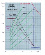
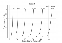
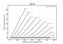
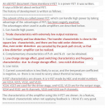
@pinholer Take a look at the attached curves measured from a 2SK79 and a 2SK82, plotted using the same x and y axis ranges. As you can see, the 2SK79 has much better linearity and more gain than the 2SK82. As mentioned by widowmaker, the 2SK82 is meant for higher power applications. (Sorry, the 2SK82 curves are a bit wiggly, because the measurement resolution was set for the typically higher power levels of this part.)
Attachments
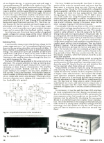
I have built several SIT amps using the Sony 2SK82 or 2SJ28 as voltage amplifiers. I also have a choke loaded LuminAria preamp using 2SK82s. My experience has been that operating these Sonys at high voltage can produce amplification with low distortion and large voltage swing. Great for driving source follower output stages.
Certainly, these Sony power VFETs may not be as good as 2SK79s, but I don't have any 2SK79s, and I have a number of the large Sonys.
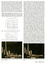
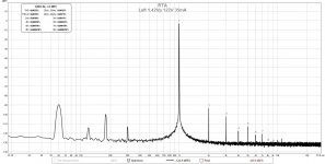
Here is an example of the measured distortion of a 2SK82 choke loaded amp operating at 122V, 35mA.
Certainly, these Sony power VFETs may not be as good as 2SK79s, but I don't have any 2SK79s, and I have a number of the large Sonys.
Here is an example of the measured distortion of a 2SK82 choke loaded amp operating at 122V, 35mA.
Attachments
The 2SK79 has very similar characteristics to a triode with that gain (gm = 14mA/V, mu = 30, rp = 2k). 2SK82/2SJ28 lose some gain in comparison. However, they have a very high gm. No signal triode has that characteristic. A low output resistance eliminates the need for an output buffer.
I root for 82/28.
I root for 82/28.
I will go back to Ditratherm story in post #63.
I saw that info in one document originated in Asia, which looked reasonably credible,
and, of course, requiring investigation.
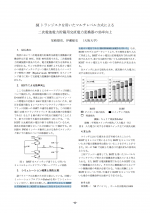
Recently, I have clarified the origins of the V### V-FETs - it is from NEC - their development
parts numbers (for the registered 2SJ19_20_21 / 2SK69_70_71).
I will attach the comments from someone in Japan, who quoted one document from the summer
of 1974, (clearly from Japanese magazine).
I saw that info in one document originated in Asia, which looked reasonably credible,
and, of course, requiring investigation.
Recently, I have clarified the origins of the V### V-FETs - it is from NEC - their development
parts numbers (for the registered 2SJ19_20_21 / 2SK69_70_71).
I will attach the comments from someone in Japan, who quoted one document from the summer
of 1974, (clearly from Japanese magazine).
Attachments
Hello,
I would like to come in contact with member Widowmaker, who posted #75 in this thread.
But at the moment I am not able to send him a PM because currently I am under moderation (what is really annoying).
Could someone else help me and send him a PM that I would like to come in contact with him?
Kind regards,
Kees.
- Home
- Amplifiers
- Pass Labs
- vFET / SIT data sheets