Yes, Gareth, I know what you mean...... I spend tens of hours on my layouts, and the last 10% of this effort seems to add a brilliant sheen to the final artform.
I certainly know about it; but others may not notice because they don't know the evolution. To me, this is the best aspect of amplifier design. The schematic is dashed off on napkinns in cafes after three coffees..... then honed in frequent ten minute sessions over a year.
Then careful analysis with LTSpice, then the pcb, then the proto, and then the production proto with all the refinements inserted to make it easy to make.
All this takes about a year. It's very slow work. But you know all this!
Cheers,
Hugh
Last edited:
There's something proper about making a layout 'look and feel right' if you know what I mean. Electrical or not, it's that feeling when something is right that often makes a project special.
Hi,
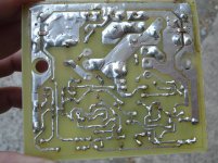
I get that feeling when I join all 90 deg traces and pads with a more elegant 45 deg angle. Dont know if its electrically significant but I like doing it and spend way too much time on it.
reg
prasi
Attachments

I like the curvy traces and have use that a few times. Not too hard to do in Sprint 6. However, Prasi's board is much smaller and I can get two of them on a single 4"x6" board so that is the one I will be doing.
I like the curvy traces and have use that a few times. Not too hard to do in Sprint 6. However, Prasi's board is much smaller and I can get two of them on a single 4"x6" board so that is the one I will be doing.
All the best for your build Terry!

you can use the larger 2SC3263/4 Sanken.
Thank you Hugh for advice- keep in mind.
I have only 3263, if we can find serious 3264 MT200 + IRFP150 or so can create a
stronger variant.
I think i am in trouble i have to order Boards, thanks the very nice worked out Bords and shared Gerbers.
Cheers Bangla.
very simple
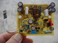
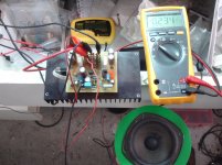
It is singing!
Using a 500R trimer for offset set i'm getting -250mV offset.
Increasing 33k to 51k it was possible to get 0mV.offset.
It is singing!
Using a 500R trimer for offset set i'm getting -250mV offset.
Increasing 33k to 51k it was possible to get 0mV.offset.
Attachments
Last edited:
very simple
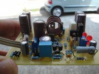
The rest.
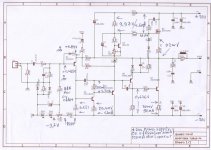
1st Offset with 500R trimer and 33k to base of inp tran.(-250mV)
2nd increasing 33K to 51K.(0mV)
In this first test two regulated power supply was used starting from +/-10v and ended up to +/-20v
The rest.
1st Offset with 500R trimer and 33k to base of inp tran.(-250mV)
2nd increasing 33K to 51K.(0mV)
In this first test two regulated power supply was used starting from +/-10v and ended up to +/-20v
Attachments

Last edited:
Some people build fast
Thanks Valery!
Using the rest of my junk box!
I will post some measurements soon.😉
Last edited:
Great work Thimios & thanks for sharing pics!!
Different rail voltages will require some fine tuning of these values as you have noted.
Different rail voltages will require some fine tuning of these values as you have noted.
Hi Ranch thanks you,AKSA and Prasi.What is the optimum bias setting?Great work Thimios & thanks for sharing pics!!
Different rail voltages will require some fine tuning of these values as you have noted.
What is the normal and what the maximum voltage for this amplifier?
My opinion about this amplifier (from a little hearing test) is that play lovely, something like a tube amplifier.
Attachments
Last edited:
Quiescent
Thimios,
I would start with 100ma and increase until you enjoy strong bass, clarity at high freq and non-fatigue presentation.
HU
ugh
Thimios,
I would start with 100ma and increase until you enjoy strong bass, clarity at high freq and non-fatigue presentation.
HU
ugh
Thanks Hugh, although a small heat sink was used just for test ,i will try to increase the current and see what i can hear.Thimios,
I would start with 100ma and increase until you enjoy strong bass, clarity at high freq and non-fatigue presentation.
HU
ugh
Last edited:
Hi guys, I've Hugh has recommended I check out this amp.... I'm going to print all these posts at work tomorrow so I can study them.... is the final PCB available from anyone?
Thanks for now..... sure there will be more questions to come!
Regards Dave
Sent from my D5833 using Tapatalk
Thanks for now..... sure there will be more questions to come!
Regards Dave
Sent from my D5833 using Tapatalk
The rest.
1st Offset with 500R trimer and 33k to base of inp tran.(-250mV)
2nd increasing 33K to 51K.(0mV)
In this first test two regulated power supply was used starting from +/-10v and ended up to +/-20v
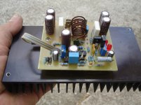
Wow! you have done it. You are faster with builds . Congrats!
Waiting for measurements...
regards
Cool, now I don't need to build.. Good job Thimios!
Terry built it!Wow! you have done it. You are faster with builds . Congrats!
Waiting for measurements...
regards
Don't leave it out of your collection!😉
Prasi thanks again for all your effort here!🙂
Hi Ranch thanks you,AKSA and Prasi.What is the optimum bias setting?
What is the normal and what the maximum voltage for this amplifier?
My opinion about this amplifier (from a little hearing test) is that play lovely, something like a tube amplifier.
The 20v rail voltage is nice from standpoint of cheap and easy to use PC SMPS bricks. Mine are 19.5v 4.6amp and two in series makes for a pretty slick little amp. This definitely looks like a lot of fun - tube sound is nice 🙂
Terry built it!
Don't leave it out of your collection!😉
Prasi thanks again for all your effort here!🙂
agree, we need your opinion about the sound
- Home
- Amplifiers
- Solid State
- Very simple quasi complimentary MOSFET amplifier