Have you try this connection?The 20v rail voltage is nice from standpoint of cheap and easy to use PC SMPS bricks. Mine are 19.5v 4.6amp and two in series makes for a pretty slick little amp. This definitely looks like a lot of fun - tube sound is nice 🙂
Two laptop power supply in series for each rail?
Have you try this connection?
Two laptop power supply in series for each rail?
Connect positive of one to negative of second and use middle tap as ground for +/-19.5v. Yes I have done this and it works. Make sure you get a SMPS with no ground prong (2 prong line connection).
Like this:
https://www.amazon.com/gp/aw/d/B005BYUWGC/
Last edited:
Connect positive of one to negative of second and use middle tap as ground for +/-19.5v. Yes I have done this and it works. Make sure you get a SMPS with no ground prong (2 prong line connection).
Like this:
https://www.amazon.com/gp/aw/d/B005BYUWGC/
exchange rate and purchasing power are bitches, in our part of the world, a proper 300VA EI transformer, diode bridge, and filter caps, will be cheaper, more practical, and less bulky
No,my question is about two power supplies in series for one rail(+)Connect positive of one to negative of second and use middle tap as ground for +/-19.5v. Yes I have done this and it works. Make sure you get a SMPS with no ground prong (2 prong line connection).
Like this:
https://www.amazon.com/gp/aw/d/B005BYUWGC/
and two other in series for (-) so we have +/-38v
No,my question is about two power supplies in series for one rail(+)
and two other in series for (-) so we have +/-38v
It can be done but you have to take great care to isolate the grounds.
No,my question is about two power supplies in series for one rail(+)
and two other in series for (-) so we have +/-38v
I've done that too with qnty 4 x 19v SMPS. Works well - I tested here:
http://www.diyaudio.com/forums/class-d/278352-pc-power-supplies.html#post4417997
Photo shows the two brick version but I also did four SMPS with +/-38v and it works too.
Last edited:
I've done that too with qnty 4 x 19v SMPS. Works well - I tested here:
http://www.diyaudio.com/forums/class-d/278352-pc-power-supplies.html#post4417997
Photo shows the two brick version but I also did four SMPS with +/-38v and it works too.
I have a lot of these from recicle
All was repaired and remained unused.
very simple
Now on the test bed.
+/-30V
36.000uF/rail
Idle current 150mA
Offset=0mV.
Not so good results🙁
I see some instability on the negative side of pulse?
Now on the test bed.
+/-30V
36.000uF/rail
Idle current 150mA
Offset=0mV.
Not so good results🙁
I see some instability on the negative side of pulse?
Attachments
Last edited:
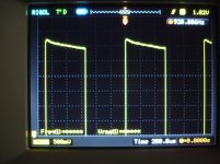
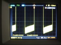
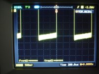
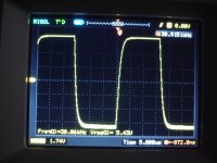
Now on the test bed.
+/-30V
36.000uF/rail
Idle current 150mA
Offset=0mV.
Not so good results🙁
I see some instability on the negative side of pulse?
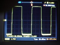
Not bad 20KHz by the way.
Yes, there is some local oscillation on the negative half-wave (you will see it on the sine wave as well). Not "fatal", but needs to be corrected.
Also, 1KHz square wave response is showing the response is rather limited at the lower end of audio bandwidth (those "spikes" in the beginning of each half-wave). Most likely, some capacitor (either input or feedback) value has to be increased.
Valery,
Quite right.... astute observations.
The negative waveform needs more LC on the base/collector of the phase inverter. This is always empirical, but I would try with 100pF, and if not enough, 150pF.
Agree with the input cap. These are quite good, actually, but there is a difference between measurements, oscillographs, and sound quality. It's one of the wonders of the world how these issues connect........
Cheers,
Hugh
My calculation shows - if you roughly double both C1 and C4 (3.3...4.7uF and 1000uF accordingly), you will have -1db at 10Hz and practically square curve at 1KHz.
Phase response at the low end will also improve.
Phase response at the low end will also improve.
Hi Valery
I said a couple of pages back that 470u is the bare minimum for the feedback cap (C4) and recommend increasing this to 2200uF. A 10V or 16V polar type is still relatively compact.
Somewhere along the line we also replaced the bipolar input cap with a small film cap to to improve sound quality. Rather than increasing the value of the film cap (it starts to get bulky) I suggest increasing R4 to 47k.
So to clean up the LF response I suggest trying:
C1 = 1.5u
R4 = 47k
R5 = increase as required
C4 = 2200u
The oscillation on the -ve half wave looks like it is caused by instability of the CFP driver/output. I don't recall seeing this on the scope when I tested mine (could be differences in silicon or board layout?) but I have seen it on other designs that use a complementary CFP output stage. Increasing the ceramic around the phase splitter should fix it up. My gut feeling is that you're going to need to increase to at least 150p, but start with 100p as Hugh suggests.
Last edited:
Hi Valery
I said a couple of pages back that 470u is the bare minimum for the feedback cap (C4) and recommend increasing this to 2200uF. A 10V or 16V polar type is still relatively compact.
Somewhere along the line we also replaced the bipolar input cap with a small film cap to to improve sound quality. Rather than increasing the value of the film cap (it starts to get bulky) I suggest increasing R4 to 47k.
So to clean up the LF response I suggest trying:
C1 = 1.5u
R4 = 47k
R5 = increase as required
C4 = 2200u
The oscillation on the -ve half wave looks like it is caused by instability of the CFP driver/output. I don't recall seeing this on the scope when I tested mine (could be differences in silicon or board layout?) but I have seen it on other designs that use a complementary CFP output stage. Increasing the ceramic around the phase splitter should fix it up. My gut feeling is that you're going to need to increase to at least 150p, but start with 100p as Hugh suggests.
Hi Ranchu,
Absolutely - makes sense.
Cheers,
Valery
Thank you all for reply.
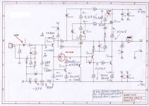
Coupling capacitor C1=2u2.(that is used)
Just to be clear,i haven't any 220pf for C10 position so a 270pf is used.
Is the value of C10 critical?
Your recommendation (to stop instability) is to increase C3 from 33pf to 100-150pf ?
Coupling capacitor C1=2u2.(that is used)
Just to be clear,i haven't any 220pf for C10 position so a 270pf is used.
Is the value of C10 critical?
Your recommendation (to stop instability) is to increase C3 from 33pf to 100-150pf ?
Attachments
Last edited:
Thank you all for reply.
Coupling capacitor C1=2u2.(that is used)
Just to be clear,i haven't any 220pf for C10 position so a 270pf is used.
Is the value of C10 critical?
Your recommendation (to stop instability) is to increase C3 from 33pf to 100-150pf ?
Hi Thimios,
Not C3 (that's a Miller correction one), but C8 - try gradually 100pF -> if still "rings" - 150pF.
Thanks Valery,i will try this soon.🙂
I will try Ranchu suggestion about 2200uf in position of feedback capacitor to eliminate low frequency roll off.
I will try Ranchu suggestion about 2200uf in position of feedback capacitor to eliminate low frequency roll off.
Last edited:
What is the greatest value for the C3 , C6 and C7 ?
greetings
What is the basis for your question? Do you have an assortment of higher value caps you wish to use or are you seeking to extract maximum performance?
There is not much benefit increasing C3 beyond the specified 47uF, although I'm fairly confident you could go an order higher (470u) without any ill effects.
I would probably step C6 from 100u up to 220u or 470u. Prolonged rail sticking is potentially an issue with larger VAS bootstrap caps but I've never found this to be an issue in practice.
C7 as specified is ample. You could use 100u if you have them but really there is no need to go higher.
Thanks.
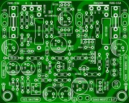
Just to make room in my PCB for these values.
2 cap 1000uf on feedback (10mm)
C3-C6-C14-C15 470uF (12mm)
C7-C1 47uF (10mm)
C8-150p
OK?
Regards
Attachments
- Home
- Amplifiers
- Solid State
- Very simple quasi complimentary MOSFET amplifier