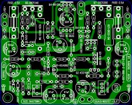
Nice single side board, Prasi, easy to make and implement!
Now, others can built it and listen to the wonderful sound.......
I trust that this Quasi amp will introduce to sound qualities of this topology.
Higher distortion than a complementary design, but wonderful sound. This might surprise a few people.....
Ciao,
Hugh
Now, others can built it and listen to the wonderful sound.......
I trust that this Quasi amp will introduce to sound qualities of this topology.
Higher distortion than a complementary design, but wonderful sound. This might surprise a few people.....
Ciao,
Hugh
Andrew you are the first!amp building in progress
warm regards
Andrew

I had lost some changes.
Here it is
Best regards
Hi,
Nice curvy layout. Some thoughts that I considered while making the layout are as follows.
1. Q1 Q2 should be close together so that they can be thermally bound.
2. feedback should be taken right at o/p connector.
3. As ranchu32 suggested, Q2 should be some distance away from Q3 to avoid the heat from Q3.
just some thoughts for you to consider.
reg
Prasi
Prasi,
1. No need to have Q1 and Q2 together; they are not a diff pair, no requirement.
2. Yes, this is significant but your layout will be fine. This is a very small issue.
3. Good point, but with 36V rail Q3 will be dissipating 255mW and Q2 only 47mW.
These are small energy prints, and if the pcb is horizontal there will be no thermal connection.
On basis, your pcb is very nice and when you mount the outputs and a heatsink, you could mount the pcb on top of the outputs and then securely the pcb attach your complete amp with just two M3s.
Very good layout!
Hugh
PS: Only a few layout software permits curvy tracks. They look nice but are not electrically important.
Thank you guys.
Sprint attached file for modifications if necessary
best regards
Could you please provide Gerber files from sprint?
Thanks.
Thanks thiagomogi!Thank you guys.
Sprint attached file for modifications if necessary
best regards
Now we have two pcb,just choose your option!😉
I have already etch a piece of prasi version.
Last edited:
Hi Christian,
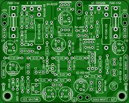
Here is the modified layout. I think this may as well be the one that will satisfy the criteria set out by Hugh and yourself (hopefully). Size is further reduced to 69mm height. now the o/p are almost at center, only about 8-9mm offset towards the top.
-1W resistor, I have increased the size to 4.6mm x 15.24mm. one may also piggy back two 0.6W resistors, if required, i think.
-C4: both 3.5mm and 5mm pitch options included.
-C6,14 and 15 sizes increased to 10mm diax3.5mm pitch. 100uF, 220uF and 330uF will fit. may be difficult to find 470uF.
and yes emitter resistor for Q2 (22R ) included.
How does it fare now?
reg
Prasi
Hi Prasi,
Can you please provide Gerbers as well when you feel it's finalized?
Thanks.
Could you please provide Gerber files from sprint?
Thanks.
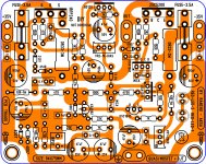
gerber attached
Attachments
Hi Prasi,
Can you please provide Gerbers as well when you feel it's finalized?
Thanks.
Sure... ver2 posted is final as it is🙂. here are the gerbs and pdfs for a ver3 that i improved silk slightly + clearances + minor trace tweaks😉. so that its more diy friendly
reg
prasi
Attachments
-
gerbs-quasi-rev3.zip136.1 KB · Views: 258
-
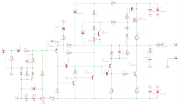
5-R3-quasi-sch.pdf37.2 KB · Views: 369
-
4-R3-quasi amp-parts and pcb-stereo.pdf681.5 KB · Views: 328
-
3-R3-quasi amp-top silk.pdf36.1 KB · Views: 282
-
2-R3-quasi amp-bottom copper.pdf250.7 KB · Views: 332
-
1-R3-quasi amp-component guide.pdf87.7 KB · Views: 362
Prasi,
1. No need to have Q1 and Q2 together; they are not a diff pair, no requirement.
2. Yes, this is significant but your layout will be fine. This is a very small issue.
3. Good point, but with 36V rail Q3 will be dissipating 255mW and Q2 only 47mW.
These are small energy prints, and if the pcb is horizontal there will be no thermal connection.
On basis, your pcb is very nice and when you mount the outputs and a heatsink, you could mount the pcb on top of the outputs and then securely the pcb attach your complete amp with just two M3s.
Very good layout!
Hugh
PS: Only a few layout software permits curvy tracks. They look nice but are not electrically important.
Thank you Hugh, for encouragement and also all of your suggestions. It has been a learning experience for me (especially design and build related)
 .
. reg
Prasi
I kick myself for getting rid of my old laser printer. Could be making my own iron transfers all this time. One thing ink jets cannot do: PCB iron on transfers.
Hallo to All.
I have followed here still reading this interesting idea and great work.
Now andrewlebon has start to build one- i am very inquisitively to see the amp finished.
Next Question for me: Can i also use Sanken SC3263 here?- they are faster?- i like the
LAPT's since i have build the Nishiki Amp from Wim de Haan.
On other Hand it is interesting to comparing sound to FetZilla Amp- i know it is an other
Animal.
Cheers Bangla.

Very nice pcb, Thiago.......
Thank you for giving it to DIYaudio.
Bangla, you can use the larger 2SC3263/4 Sanken. This would be ideal if you use the nmos to a 280W version, then you could push up the rail voltage to over 50V for much more power.
Cheers,
Hugh
Thank you for giving it to DIYaudio.
Bangla, you can use the larger 2SC3263/4 Sanken. This would be ideal if you use the nmos to a 280W version, then you could push up the rail voltage to over 50V for much more power.
Cheers,
Hugh
Member
Joined 2009
Paid Member
PS: Only a few layout software permits curvy tracks. They look nice but are not electrically important.
There's something proper about making a layout 'look and feel right' if you know what I mean. Electrical or not, it's that feeling when something is right that often makes a project special. I love the attention to detail in this pcb's curves.
- Home
- Amplifiers
- Solid State
- Very simple quasi complimentary MOSFET amplifier