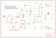
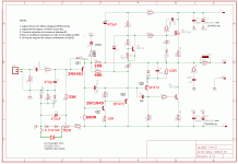
This is awesome, a nice as built schematic, time to pass a Digikey order.!
Congrats on the singing amps.
What are BF470, never heard about these. Could you suggest an equivalence please ?
BR
Eric
Congrats on the singing amps.
What are BF470, never heard about these. Could you suggest an equivalence please ?
BR
Eric
Last edited:
Hi Eric,
BF470 is a TO126 250V Philips pnp device from the seventies. They are cheap, but a bit slow, around 60MHz. I would suggest Fairchild KSA1381, they are around 150MHz and good dissipation.
Cheers,
Hugh
BF470 is a TO126 250V Philips pnp device from the seventies. They are cheap, but a bit slow, around 60MHz. I would suggest Fairchild KSA1381, they are around 150MHz and good dissipation.
Cheers,
Hugh
Hello guys.
My amplifier sings .
I had the same problem xrk DC offset.
I changed some values and could 0v DC .
BIAS is solid.
Tomorrow I'll take ESCOPE for some waves.
Congrats!

Hi Eric,
BF470 is a TO126 250V Philips pnp device from the seventies. They are cheap, but a bit slow, around 60MHz. I would suggest Fairchild KSA1381, they are around 150MHz and good dissipation.
Cheers,
Hugh
I ran out of KSA1381's and am using MJE350. Works very well and I believe they are quite fast too.
I ran out of KSA1381's and am using MJE350. Works very well and I believe they are quite fast too.
If we whant to help other buil ders,it is necessery a final schematic diagram
Last edited:
Hi.
Very nice thiagomogi- you have a singing Amp on extraordinary board.
You have used the last part list with Ranchu's part changed- prasi has send an Excel,
must be round page 57-59.
With this list i also work.
One little question to Hugh: Is it better to start R5, like Terry with 51k or could i use
68k too?- i see i have 100k there and 2 x red LED- will see next week.
Cheers Bangla.
Hi Bangla,
I have redrawn Thiago's schematic with my suggested values for best sound.
It really is best to leave R5 at 33k, do not change it, and alter the trimmer to get the offset correct. R4 should be deleted completely. With the values given this quasi should give a good range of offset. I have left 2 x 1N4148 diodes on the offset reference, BUT, to improve the range so that the 500R trimpot is set more midpoint, I would suggest dropping to the two diodes and put ONE green LED which gives 2V of reference and a nice indicator lamp.
Cheers,
Hugh
Attachments
Last edited:
Hi Hugh.
Thank you, very kind, your help.
I will desolder- crossed fingers- remind x- the two resistors and put in 33k.
Cheers Bangla.
Thank you, very kind, your help.
I will desolder- crossed fingers- remind x- the two resistors and put in 33k.
Cheers Bangla.
Hi Hugh,
When you suggest dropping 2 diode you are talking for sure the 2 1N4148 in serie? Yes ?
Would the above schematic need changes to use KSA1381 insted BF470?
Marc
When you suggest dropping 2 diode you are talking for sure the 2 1N4148 in serie? Yes ?
Would the above schematic need changes to use KSA1381 insted BF470?
Marc
My pleasure, Bangla,
Note however that I have changed the fb resistor R9 from 1k5 to 1k8, and I suggest R8 (I missed this) should be increased to 68R. This is to keep the gain at around 27 (about 28dB). I also suggest that 2,200uF will create huge thumps at switchon, and I feel 470uF is just fine here. The phase shift and frequency below 20Hz will not be important.
Yes, Marc,
The two 1N4148s would be in series (1.3V) and a single LED green would give you just under 2V. The wiper will need around -2.88V to ensure the offset at 0mV. This will be -2.54V at the base of the first transistor.
Cheers,
Hugh
Last edited:
Thank you very much, Thimios, I hugely appreciate it......
I was a little tired after my last (it is 10:30pm and I am about to retire...... old man!) and I admit I did not fill out all my details. This should be very clear now, besides, green is so much better than red, or nothing at all.
Cheers,
Hugh
I was a little tired after my last (it is 10:30pm and I am about to retire...... old man!) and I admit I did not fill out all my details. This should be very clear now, besides, green is so much better than red, or nothing at all.
Cheers,
Hugh
I hope this will be final🙂
THimios didn't you forget the last Hughs advice? Replacing the 2200uf by a 470uf.
Marc
It's funny, I used 470uF originally because I did not have any 2200uF ones. Lucked out on that. I noticed that, per Aksa's advice, I am using 1k at R7 and R9 and DC offset adjustment range seems fine.
THimios didn't you forget the last Hughs advice? Replacing the 2200uf by a 470uf.
Marc
I don't think he forgot, C6 should be 470uF and C4 in the feedback loop remains 2200uF.
Hugh to confirm this.
Also, wasn't there a small compensation cap across the feedback resistor R9, it seems gone from Thimios final schematic.
Eric
Last edited:
Hi,
R5 is now 33k
R4 is out.
DC off set is 0 .
I now have two channels sing.
I'll have the opportunity to listen and then come back with impressions and measurements.
Thanks Hugh for all efforts to guide us.
Regards
R5 is now 33k
R4 is out.
DC off set is 0 .
I now have two channels sing.
I'll have the opportunity to listen and then come back with impressions and measurements.
Thanks Hugh for all efforts to guide us.
Regards
Hi,
R5 is now 33k
R4 is out.
DC off set is 0 .
I now have two channels sing.
I'll have the opportunity to listen and then come back with impressions and measurements.
Thanks Hugh for all efforts to guide us.
Regards
R4 out is key to getting adjustability of offset. Installing 1N4148's instead of two LEDs was key to getting offset span to be in right range.
Great news that you are up and running in stereo. We look forward to listening impressions.

I see that you guys have changed the trimmer to 500R. Can one or both of you measure you trimmer and let us know where it is set? I'm curious how close to center you are.
Thanks, Terry
Thanks, Terry
- Home
- Amplifiers
- Solid State
- Very simple quasi complimentary MOSFET amplifier

