I see that you guys have changed the trimmer to 500R. Can one or both of you measure you trimmer and let us know where it is set? I'm curious how close to center you are.
Thanks, Terry
I am right at the edge of the 500R pot right now: 7ohms on one and 13ohms on the other. Certainly something external could still be done to center the DC offset on the trimpot more. But as it is, there is plenty of room to adjust as it is pretty sensitive to small adjustments.

Hi Thiagomogi,
Is that schematic your asbuilt? It is a little different than what Hugh is specifying. Is your layout set up for the BC550 transistors or did you have to twist wires? Looks like you kept R4 at 47k.
Thanks for posting this.
Is that schematic your asbuilt? It is a little different than what Hugh is specifying. Is your layout set up for the BC550 transistors or did you have to twist wires? Looks like you kept R4 at 47k.
Thanks for posting this.
Hi Guys,
Now I'm up and running again......
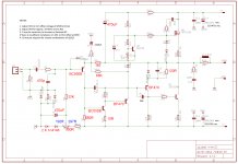
Reasons (refer to Thiago's schem #1005 above).
I moved to 1k8 (R9) so that I could increase the shunt resistor from 47R (R8) to 68R, taking the pressure on a very large shunt cap. With 68R 470uF is very good bass; you don't need a larger C4 2,200uF. I increased the current from 0.7mA to mA through Q1 with decrease from 1k (R7) to 680R collector load because the noise and gainwidth is superior for the 5401 at 1mA, and certainly this put pressure on the input impedance.
Let me figure the offset voltages, so it's clear where these values come from.
Assume the output sits at 0mV.
All the current for Q1 can only come from the output node (R9 and R10), and it's determined by R9 since 1k5 is far less than 68k. There is a difference of 2.2% but it can be ignored here.
So, 1mA comes through 1k8, and this drops 1.8 volts - giving us -1.8V wrt ground. Remember, this is negative voltage because it LOWER potential than the ground.
Now, the base of 2N5401 (Q1) lies 0.65V below the voltage at the emitter; if we figure out the base voltage is is now -2.45V wrt ground.
The base current must be calculated for Q1 now because it must come from R5 (33K) since all DC currents elsewhere are blocked by caps. Note also that R4 is DELETED, because it is were there it would be supplying base current from a 0V potential which would interfere with our bias voltage.
We assume Q1 has a beta of 100. This is an estimate but it's close. If collector is passing 1mA, then the base will need 1/100 mA to turn it on to this point, and since it passes through R5 33k, the voltage dropped across this bias resistor is 1/100 x 33 = 0.33V. Add this NEGATIVE voltage (it has to be across R5 33k and if the base is at -2.45V it must be lower) we have -2.45V + (-0.33V) = -2.78V.
So, we need -2.78V, plus or minus a few mV, to bias the output of the amp at 0mV.
Let's examine the diode/LED string which supports this bias voltage, D1/D2 and trimmer.
I'm in trouble with time.........
You best need the LED, green, here.
Cheers,
Hugh
Now I'm up and running again......
Reasons (refer to Thiago's schem #1005 above).
I moved to 1k8 (R9) so that I could increase the shunt resistor from 47R (R8) to 68R, taking the pressure on a very large shunt cap. With 68R 470uF is very good bass; you don't need a larger C4 2,200uF. I increased the current from 0.7mA to mA through Q1 with decrease from 1k (R7) to 680R collector load because the noise and gainwidth is superior for the 5401 at 1mA, and certainly this put pressure on the input impedance.
Let me figure the offset voltages, so it's clear where these values come from.
Assume the output sits at 0mV.
All the current for Q1 can only come from the output node (R9 and R10), and it's determined by R9 since 1k5 is far less than 68k. There is a difference of 2.2% but it can be ignored here.
So, 1mA comes through 1k8, and this drops 1.8 volts - giving us -1.8V wrt ground. Remember, this is negative voltage because it LOWER potential than the ground.
Now, the base of 2N5401 (Q1) lies 0.65V below the voltage at the emitter; if we figure out the base voltage is is now -2.45V wrt ground.
The base current must be calculated for Q1 now because it must come from R5 (33K) since all DC currents elsewhere are blocked by caps. Note also that R4 is DELETED, because it is were there it would be supplying base current from a 0V potential which would interfere with our bias voltage.
We assume Q1 has a beta of 100. This is an estimate but it's close. If collector is passing 1mA, then the base will need 1/100 mA to turn it on to this point, and since it passes through R5 33k, the voltage dropped across this bias resistor is 1/100 x 33 = 0.33V. Add this NEGATIVE voltage (it has to be across R5 33k and if the base is at -2.45V it must be lower) we have -2.45V + (-0.33V) = -2.78V.
So, we need -2.78V, plus or minus a few mV, to bias the output of the amp at 0mV.
Let's examine the diode/LED string which supports this bias voltage, D1/D2 and trimmer.
I'm in trouble with time.........
You best need the LED, green, here.
Cheers,
Hugh

OK, I'm back at the cafetaria - to continue......
We need -2.78V at the bottom of the 33k bias resistor.
If we replace the two 4148s with a SINGLE green LED, then we have the anode of the LED at ground and the cathode at -1.95V.
The 500R trimmer comes next then the 10k supply resistor which sets the LED and trimmer current. If we have a -35V supply, then the current will be (35 - 1.95)/(10 +0.5) = 3.2mA.
With this current can calculate the trimmer range.
3.2mA across 500R is 1.6V; we start with -1.95V so we can adjust the down to -3.55V. We need a voltage of -2.78V so this should be fine and around the mid-point of the range.
Cheers
HD
Wow Hugh, where have you been all this time? I can see why Carlos is in love with you. I think I have learned more from you in the last two weeks than I have since I started this hobby. Thank you, thank you, thank you!!
Blessings, Terry
Blessings, Terry
Wow Hugh, where have you been all this time? I can see why Carlos is in love with you. I think I have learned more from you in the last two weeks than I have since I started this hobby. Thank you, thank you, thank you!!
Blessings, Terry
I agree.
This amp has been a lot of fun and a great lesson for me
Thanks Hugh
Regards
Thiago
Thanks Guys!
The idea is to be transfer some of the truth to dispel some of the bull!@#$ I see in this hobby.
It's actually very simple, Ohms Law, and Kirchoff's Rule. The AC theory is more complex, but to get an amp to run you basically need only DC theory. Most of the nonsense applies to the AC theory, where people are unable to comprehend the math, and so the buyer is vulnerable to snake oil, like cables.
This is a multilingual site, and it is a credit to guys from other languages who take part so effectively. I relate to you guys because after a mild stroke I developed serious aphasia. This messes with the speech area of the brain and causes grammar, syntax and lexicon issues. I came out with two languages arguing in my head and only Indonesian people with good English could understand what I was saying. I would say RED, but meant BLUE, or FAST and used the word CEPAT. I knew what I meant, but others thought it was gibberish. This is a wonderful experience for someone learning and/or using another language; so when I recovered reasonably well - lumayan saja - I decided to keep my sentences simple so that others could easily figure out what I was saying.... The choice of prepositions, conjunctions and pronouns is critical in any language, and so many who use English first language need to be precise and correct, and keep away from slang (local language).
The other issue is that I know that my life is limited. It would be a waste of what I have learned to have died without transferring any of it. Not many people are interested in analog audio in my city, so this forum is important. My approach is a form of narcissism; we would all like to be remembered after we fall of the branch....... Because my knowledge is much less than many but precisely because it is very practical, I thought it would be nice to put some of it on 'paper', chronical some of the 'fixes' so hobbyists can search and find tough problems into the future.
I am touched that you guys have listened. Thanks.... I have actually designed a pcb for a stereo quasi with power supply but Christian and I are stuggling with the Protel software, which cannot produce good gerbers. They are shrunk by a factor of 7 times! I have just purchased DipTrace Lite, and now I'm going to throw myself into deep water to learn how to use it..... to the level of Protel. It will be difficult!
Thanks to Terry, and Thiago. You guys are very skilled at what you do, and we need builders, listeners, layout experts, and designers. All have a part in this wonderful hobby we are all fascinated by.
Cheers,
Hugh
Last edited:
I have also learned much from Hugh in the past couple of weeks. Adversity with this amp has taught me a lot. Ohms law and Kirchoff's rule are all you need to get the DC analysis for the amp to work. The simulation software is great - but being able to work out the basics with pencil and paper line this is priceless. In grad school, my former advisor taught all students in his group you just need to know one "hip pocket number" to solve the basics of most chemistry and fluids physics problems: the kinetic gas collision rate =10 collisions per nanosecond at STP. From that, you could work out most answers within factor of 2x to 5x and enough to check things for gross errors or BS.
I feel like Hugh has taught me the equivalent in amps. Start with balanced desired output of 0mV and see what currents and voltages need to be at nodes to achieve that.
It's a privilege to have Hugh take the time to explain in detail like this.
Thank you, Hugh!
Cheers,
X
I feel like Hugh has taught me the equivalent in amps. Start with balanced desired output of 0mV and see what currents and voltages need to be at nodes to achieve that.
It's a privilege to have Hugh take the time to explain in detail like this.
Thank you, Hugh!
Cheers,
X
OK, I'm back at the cafetaria - to continue......
We need -2.78V at the bottom of the 33k bias resistor.
If we replace the two 4148s with a SINGLE green LED, then we have the anode of the LED at ground and the cathode at -1.95V.
The 500R trimmer comes next then the 10k supply resistor which sets the LED and trimmer current. If we have a -35V supply, then the current will be (35 - 1.95)/(10 +0.5) = 3.2mA.
With this current can calculate the trimmer range.
3.2mA across 500R is 1.6V; we start with -1.95V so we can adjust the down to -3.55V. We need a voltage of -2.78V so this should be fine and around the mid-point of the range.
Cheers
HD
Hi Hugh,
Thank you for your clear explanation. But why prefer bias preset in series with voltage reference diode/LED. By this method bias voltage will vary with supply voltage. Trimmer current is 3.2 ma for 35V supply,2.67ma for 30V supply and 3.62 ma 40 supply . Voltage across trimmer is 1.6V,1.33V and 1.81V.This clearly shows bias will change with the mains supply.
If we connect the preset parallel with two series connected LED will solve the issue. Two series connected LED have almost constant 3.8V across it. 1k preset in series with 1k resistor provide constant 1.9v to 3.8v viper voltage.So more stable bias and betters PSRR.
Or something special for this series connected method?
Best Regards
joshvi
Yes, Joshvi,
You can do this without problem but when you increase the rail voltage of any amplifier you often find that the offset moves too. With my earlier suggestion (and it is a suggestion, nothing more) the changes are small, no more than 200mV either way, and you would always check offset anyway with a higher voltage.
The two facts you first check with an audio, direct coupled amp are OFFSET and QUIESCENT. If both are perfect, then you have 98% certainty it is in operational use.
Cheers,
Hugh
Hi Hugh,
Thank you for your reply. Yes , only 200-250 mv offset drift. But country like India mains voltage variation is high. As high as 15-20 %.
Best Regards
joshvi
Thank you for your reply. Yes , only 200-250 mv offset drift. But country like India mains voltage variation is high. As high as 15-20 %.
Best Regards
joshvi
The other issue is that I know that my life is limited. It would be a waste of what I have learned to have died without transferring any of it. Not many people are interested in analog audio in my city, so this forum is important. My approach is a form of narcissism; we would all like to be remembered after we fall of the branch....... Because my knowledge is much less than many but precisely because it is very practical, I thought it would be nice to put some of it on 'paper', chronical some of the 'fixes' so hobbyists can search and find tough problems into the future.
I can see lot of my qualities in you . I teach a lot in embedded to my subordinates . I am also learning here . In a selfish world we are gifted to have you here.
joshvi by your method the bias voltage will be constant even if the rail voltage varies . but since rail voltage has changed the standing current in q1 will vary which results in MORE deviation in offset voltage. (no automatic correction)
as per Hugh method the bias voltage will vary with rail voltage which results in LESS deviation in offset voltage.(at least some automatic correction)
Request builders to post more comments on sound quality .
I am yet to start building amps . need to collect required components (difficult to get all in india).
Thanks Guys!
The idea is to be transfer some of the truth to dispel some of the bull!@#$ I see in this hobby.
It's actually very simple, Ohms Law, and Kirchoff's Rule. The AC theory is more complex, but to get an amp to run you basically need only DC theory. Most of the nonsense applies to the AC theory, where people are unable to comprehend the math, and so the buyer is vulnerable to snake oil, like cables.
This is a multilingual site, and it is a credit to guys from other languages who take part so effectively. I relate to you guys because after a mild stroke I developed serious aphasia. This messes with the speech area of the brain and causes grammar, syntax and lexicon issues. I came out with two languages arguing in my head and only Indonesian people with good English could understand what I was saying. I would say RED, but meant BLUE, or FAST and used the word CEPAT. I knew what I meant, but others thought it was gibberish. This is a wonderful experience for someone learning and/or using another language; so when I recovered reasonably well - lumayan saja - I decided to keep my sentences simple so that others could easily figure out what I was saying.... The choice of prepositions, conjunctions and pronouns is critical in any language, and so many who use English first language need to be precise and correct, and keep away from slang (local language).
The other issue is that I know that my life is limited. It would be a waste of what I have learned to have died without transferring any of it. Not many people are interested in analog audio in my city, so this forum is important. My approach is a form of narcissism; we would all like to be remembered after we fall of the branch....... Because my knowledge is much less than many but precisely because it is very practical, I thought it would be nice to put some of it on 'paper', chronical some of the 'fixes' so hobbyists can search and find tough problems into the future.
I am touched that you guys have listened. Thanks.... I have actually designed a pcb for a stereo quasi with power supply but Christian and I are stuggling with the Protel software, which cannot produce good gerbers. They are shrunk by a factor of 7 times! I have just purchased DipTrace Lite, and now I'm going to throw myself into deep water to learn how to use it..... to the level of Protel. It will be difficult!
Thanks to Terry, and Thiago. You guys are very skilled at what you do, and we need builders, listeners, layout experts, and designers. All have a part in this wonderful hobby we are all fascinated by.
Cheers,
Hugh
Thank you very much sir, hats off to you for your encouragement and knowledge sharing. Like Terry said, I learnt more here on this thread than anywhere. I am sure you will keep on guiding us for a long long time here.
best regards
Prasi
Request builders to post more comments on sound quality .
A comparison with my inverted JFET Circlophone may be the closest in topology as it has a quasi output stage, but has differential input JFET pair.
I really do enjoy listening to this Simple MOSFET Quasi amp - for the past few days it has gone through many songs and I have enjoyed them all. So overall presentation is very pleasant and dynamics are excellent. Bass authority feels very powerful and deep to me.
I just switched back to the Circlophone and based on memory, I think the vocals sound "less full" and bass seems drier and more crisp. I would guess that the simple quasi has euphonic even order harmonic structure that gives it the fuller warmer sound. Tube-like is how some may say it sounds.
It's a great amp though and wants to make you stay up late and listen more and more - which says a lot. It's definitely going to get a more permanent case at some point.
........... for a long long time ................
Yes,, Hugh ......and all of us.........will be around for a very VERY long time ! Not necessarily in the present 'package' ! Would we need DIYaudio support .... it is to be determined at a later point of time..........🙂
I can see lot of my qualities in you . I teach a lot in embedded to my subordinates . I am also learning here . In a selfish world we are gifted to have you here.
joshvi by your method the bias voltage will be constant even if the rail voltage varies . but since rail voltage has changed the standing current in q1 will vary which results in MORE deviation in offset voltage. (no automatic correction)
as per Hugh method the bias voltage will vary with rail voltage which results in LESS deviation in offset voltage.(at least some automatic correction)
Request builders to post more comments on sound quality .
I am yet to start building amps . need to collect required components (difficult to get all in india).
Can you explain this? What do you mean by standing current of q1 ? if you mean, the bias current of q1 then tell me how the automatic correction happen?
I am looking for clear explanation like what Hugh did. I am very clear what he explained.
I am not a newbee to electronics. if I am wrong I am ready to accept.
Not looking for any bla bla
Best regards
Joshvi
Here is my two cents. I was intrigued with this concept of combination MOSFET - BJT OPS.
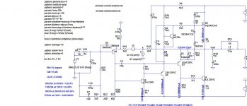
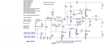
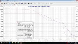
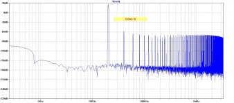
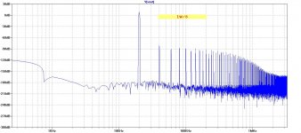
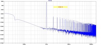
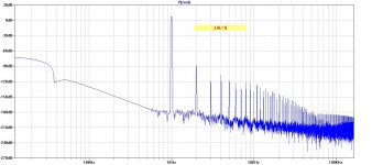
I simulated quasi with lower cap 15pF(I think it's should be stable even with thi value) and than tried the same amp with TPC.
THD at 20 kHz dropped significantly but not as much as I expected(looking the Loop Gain plot). The reason for that, in my opinion, is two week drive of the output transistor(more visible at higher frequencies when output transistor came to play).
Additional local NFB around VAS, in my opinion does not do any good to the sound, and I removed it. All plots are for TPC version.
Damir
Attachments
- Home
- Amplifiers
- Solid State
- Very simple quasi complimentary MOSFET amplifier