Just to make sure I have this correct, I have 2 choices with the inputs connected to the amp:
1. Short the inputs directly at the input rca jacks or,
2. Short the input wires at the amp input using a wire or alligator clip.
In either case the input wires are connected to the amp input and not removed, only shorted.
Have I got it 🤔
1. Short the inputs directly at the input rca jacks or,
2. Short the input wires at the amp input using a wire or alligator clip.
In either case the input wires are connected to the amp input and not removed, only shorted.
Have I got it 🤔
Short the input wires at the amp input using a wire or alligator clip.Just to make sure I have this correct, I have 2 choices with the inputs connected to the amp:
1. Short the inputs directly at the input rca jacks or,
2. Short the input wires at the amp input using a wire or alligator clip.
In either case the input wires are connected to the amp input and not removed, only shorted.
Have I got it 🤔
do this way.
Hi,
I am having problems with both of the amp channels. I am describing below what I feel is the easiest problem to fix.
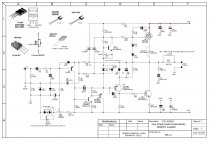
I am having problems with adjusting the offset voltage below 2.0V. I have built as per the attached schematic and pcb board. I am having no problems with the setting the bias. If I remember correctly stillforgiven and xrk971 had these problems also. Not sure if changing the value of R5 is the way to solve this problem.
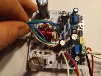
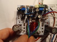
I can also mention that I have no leds installed, only recommended diodes as per schematic. I have visually checked solder joints and as far as I can tell, components are installed correctly. I am using 200R trimmer to set offset voltage. 0.33R resistors R20 & R21 are underneath the boards. Please see attachments and thanks for any trouble shooting tips. Tried to keep wires out of the way to show components.
MM


I was reading some of the threads (I have downloaded and edited a lot of them to remember important knowledge) concerning the use of led vs diodes. Xrk used only a blue led and did not populate D7 the 3V3 diode. No red led; used 2 1N4148 instead. This enabled Xrk to set the offset voltage to 2-3mV.
Could use some advice before making any changes (Note: I realize that people are celebrating holidays ).
).
MM
Could use some advice before making any changes (Note: I realize that people are celebrating holidays
 ).
).MM
Hello Kokanee,
some linked points where you can start for needed informations, hope that works for your need.
https://www.diyaudio.com/community/...imentary-mosfet-amplifier.255427/post-4765841
https://www.diyaudio.com/community/...imentary-mosfet-amplifier.255427/post-4770076
https://www.diyaudio.com/community/...imentary-mosfet-amplifier.255427/post-4773925
About R5-
https://www.diyaudio.com/community/...imentary-mosfet-amplifier.255427/post-4774953
https://www.diyaudio.com/community/...imentary-mosfet-amplifier.255427/post-4778715
https://www.diyaudio.com/community/...imentary-mosfet-amplifier.255427/post-4781262
Wish all the best for next New Year.
Thanks for the help BH. I had / have read these as they have valuable info. I think I may start with changing R5 to either 68k or 100k ohms. If this does not fix the offset voltage, then I will change the 200R pot to a 500R pot and see if that works. Last resort will be working on the led/diodes. May take awhile, as holidays are happening in 10 days, and will not be back until end of April.
Hello
i have kept this post by Hugh
https://www.diyaudio.com/community/...imentary-mosfet-amplifier.255427/post-4796245
I have build it mostly that way
But: Q1- 992; Q2-1845; Q3,5- 1381; C4-1000µ/16( better going as advised); R5-actual 100k; D7-3,3v zehner
Thanks again to Hugh for claryfiing that important point about R5, i will change it too...if i start building again, all stopped since
nearly two years now.
Earlyer was refered about that reference LED- a green one (~1,6V) or 2 x 4148 string that should give ~1,3V.
I hope i not confuse things now anymore. 😳
Hope you will figure out it.
Best wishes for a good start to 2023, good hollidays too.
Thanks for the help Bangla H and Hugh,
1. Hugh, according to the Dacz schematic that is posted in #2663. It quotes: " If green led is used, remove D9-D10 and jump D10".
2. Hugh, you are recommending using a blue led in place of one of the diodes D9 or D10.
Which of the above is better option as I have used a 200R pot as VR1 referenced on pcb, and, not the 500R pot that is referenced on the schematic.
I assume that we are trying to lower the voltage dropped by combinations of leds and diodes. Is my thinking correct, maybe I have it backwards ?
MM
I think that is time Hugh repost a final schematic diagram again here.Thanks for the help Bangla H and Hugh,
1. Hugh, according to the Dacz schematic that is posted in #2663. It quotes: " If green led is used, remove D9-D10 and jump D10".
2. Hugh, you are recommending using a blue led in place of one of the diodes D9 or D10.
Which of the above is better option as I have used a 200R pot as VR1 referenced on pcb, and, not the 500R pot that is referenced on the schematic.
I assume that we are trying to lower the voltage dropped by combinations of leds and diodes. Is my thinking correct, maybe I have it backwards ?
MM
It is a big confusion readings so many different modifications.
I will post a schematic later; I'm sending off a family member to the US right now!
To recap the concept, there is no change to the aim; to simply change the voltage reference for the input base transistor.
If you have +2V offset, you have to put 2V MORE negative on the base voltage of T1, and this means playing with the drop across the two diodes, nothing more. Any change to R5 affects feedback, a definite no. Because of stacking tolerances on this amp (hfe and Vbe of T1) it is difficult to ensure that the offset control pot will always be in the center, so some adjustment is needed.
Give me a few hours and I will draw it up.
Hugh
I will post a schematic later; I'm sending off a family member to the US right now!
To recap the concept, there is no change to the aim; to simply change the voltage reference for the input base transistor.
If you have +2V offset, you have to put 2V MORE negative on the base voltage of T1, and this means playing with the drop across the two diodes, nothing more. Any change to R5 affects feedback, a definite no. Because of stacking tolerances on this amp (hfe and Vbe of T1) it is difficult to ensure that the offset control pot will always be in the center, so some adjustment is needed.
Give me a few hours and I will draw it up.
Hug
All the time is your's🙂I will post a schematic later; I'm sending off a family member to the US right now!
To recap the concept, there is no change to the aim; to simply change the voltage reference for the input base transistor.
If you have +2V offset, you have to put 2V MORE negative on the base voltage of T1, and this means playing with the drop across the two diodes, nothing more. Any change to R5 affects feedback, a definite no. Because of stacking tolerances on this amp (hfe and Vbe of T1) it is difficult to ensure that the offset control pot will always be in the center, so some adjustment is needed.
Give me a few hours and I will draw it up.
Hugh
Hi Myles, Thimios,
We can use Myles' schematic from DACZ posted in 2016, but referred on page 133 of this thread.
We focus on D9 and D10, the two IN4148 diodes which comprise part of the voltage reference for the offset system.

If you have +2V offset at the output, then we need to add 2V NEGATIVE to the bias resistor, R5.
D9 and D10 pass about 4mA, and drop around 1.4V. We need to increase this drop to 1.4+2=3.4V.
Easiest way to do this is remove BOTH the diodes, which drop 1.4V, and replace with an LED which drops close to 3.4V.
The optimal LED is a blue, as they drop about 3.3V, close enough for government work here!
OR, you could drop ONE of the diodes, and replace with a green LED which drops 1.95V, so this will add 1.25V, not quite enough.
We have to get to 3.4V, and the best is a blue LED.
R5 is the bias resistor of the base of T1, and if you change it you change the input impedance of the amp which could be problematic for the source. Best to leave it at 33k, which sets the Zin of around 25k, easy to drive.
Hugh
T
We can use Myles' schematic from DACZ posted in 2016, but referred on page 133 of this thread.
We focus on D9 and D10, the two IN4148 diodes which comprise part of the voltage reference for the offset system.
If you have +2V offset at the output, then we need to add 2V NEGATIVE to the bias resistor, R5.
D9 and D10 pass about 4mA, and drop around 1.4V. We need to increase this drop to 1.4+2=3.4V.
Easiest way to do this is remove BOTH the diodes, which drop 1.4V, and replace with an LED which drops close to 3.4V.
The optimal LED is a blue, as they drop about 3.3V, close enough for government work here!
OR, you could drop ONE of the diodes, and replace with a green LED which drops 1.95V, so this will add 1.25V, not quite enough.
We have to get to 3.4V, and the best is a blue LED.
R5 is the bias resistor of the base of T1, and if you change it you change the input impedance of the amp which could be problematic for the source. Best to leave it at 33k, which sets the Zin of around 25k, easy to drive.
Hugh
T
Sounds good Hugh, thanks for the explanation. I had it all backwards, thinking that we would have to reduce the + 2.0 volts so a reduction was necessary. It is a good day when one learn something. Let me check my led supply and see what I have.
Will report back after modifications.
MM
Will report back after modifications.
MM
OK, I desoldered D9 and D10. I soldered in the blue led. I checked the blue led in the circuit with DMM and it lights up. Applied the power thru variac and DBTester with no sparks or fire. All transistors are warm and heatsink is warm.
One problem: blue led does not light up. Do I need to insert a jumper at D10 as per the Dacz schematic?.
Thanks for the help,
MM
One problem: blue led does not light up. Do I need to insert a jumper at D10 as per the Dacz schematic?.
Thanks for the help,
MM
While I was waiting for a reply to the above post. I thought I would see what the DC offset was. The DC offset started at about -2.1V and slowly over the span of about 30 minutes went down to OmV and began to slowly climb on the +mV side. At this point I adjusted the trimmer to keep the DCV in the low +/- mV range. The voltage movement was not smooth as the values jumped between a range of 50mV between readings. Hope this makes sense.
MM
MM
Yes, Myles, if you can't straddle the blue LED from anode D9 to cathode D10, jumper D10 so you only use only D9 spot to insert the LED.
I'm not so sure why the offset very slightly rose. This might be a slowly rising negative rail voltage, which would not be good, or it could be something to do with the C3 22uF bias cap. It could be high, maybe 220uF perhaps? Or installed with wrong polarity?
Nearly there........
Hugh
I'm not so sure why the offset very slightly rose. This might be a slowly rising negative rail voltage, which would not be good, or it could be something to do with the C3 22uF bias cap. It could be high, maybe 220uF perhaps? Or installed with wrong polarity?
Nearly there........
Hugh
Thanks Hugh, I inserted the blue led where it was shown on the pcb (actual spot for green led) and removed both D9 and D10. I will insert a jumper wire for D10. Will report back and will also check C3.
So, I straddled the led from anode D9 to cathode D10, cleaned up the pcb and powered up. The led lit up and the DC was all mV. I could only adjust to an average value of 150mV +/- 15 mV with the 200R trimmer. Not sure why the offset voltage is jumping around so much?
Also, I checked C3, it is 22uF and is installed correctly.
Do I need a different trimmer? or, is there more tricks to try. Help is always appreciated
Also, I checked C3, it is 22uF and is installed correctly.
Do I need a different trimmer? or, is there more tricks to try. Help is always appreciated
Hi Myles
I would replace R6 10k for a 15k
Then replace the trimmer with 500R version.
I was not aware you using a 200R trim pot.
This will reduce LED current from 4ma to 2.7ma and reduce its drop from 3.3V to 3.1V.
This should fix the offset issue.
Hugh
I would replace R6 10k for a 15k
Then replace the trimmer with 500R version.
I was not aware you using a 200R trim pot.
This will reduce LED current from 4ma to 2.7ma and reduce its drop from 3.3V to 3.1V.
This should fix the offset issue.
Hugh
- Home
- Amplifiers
- Solid State
- Very simple quasi complimentary MOSFET amplifier