Hi Peter,
My tubes arrived for the ECC88 boards. They are the 6N1P tubes. I'm looking back through the thread and I don't see instructions for setting R9 trimpot. Can you explain that for me please?
Thanks, Terry
Yes I remember right, Terry uses different Russian tube
Terry you should look for 6DJ8 a tone available in N America or ECC type mostly from Europe.
My humble advise
greetings 🙂
Yes I remember right, Terry uses different Russian tube
Terry you should look for 6DJ8 a tone available in N America or ECC type mostly from Europe.
My humble advise
greetings 🙂
Yes the 6N1P is not equal with ECC88. But it's a good tube generally. Worth enough to give it a chance. Gain is high too, so increment of the cathode resistors can be a solution...
And I would set 3mA for this tube too. (The best check is to measure the voltage across the anode resistors).
Sajti
There is a lot of interest; yes, the 6CG7 is identical to the 6SN7-GTB as described in the Sylvania datasheet (check it to be sure!).
May I suggest something? The schematic uses a pinout of the tube rather than the standard triode symbol, so it is a bit cryptic trying to figure out the circuit.
I mentioned some time back that the Onkagu, that $130k Japanese SET amp that dominates standards of audiophile standards, uses a SRPP 6SN7 as input stage at 107V B+. That is around 50V Vak on each triode, and it might be a good idea to mimic this operating point on this amp, but it will need increasing the rails to 50V, which is a good idea as it would enable output to around 100W//8R. I seen to remember that it ran at 2mA IIRC.
The plate load of this triode is the 1k5 on the 12AU7 and this is a stiff load. This value will set the stage current of the VAS and is critical, should be correct. In this use the current through the triodes changes very, very little. They used as pure transconductance devices, very little voltage change at the plates in use.
Most hybrid amps need a separate, expensive power supply for the tube. This circuit does not, and is very easy to build. The only concern is the switch on, which is at least 11 seconds to stabilise the offset. Accordingly, I would suggest a single 100V rail, and this would require a coupling cap at the output - ensuring offset controls during switch-on AND speaker protection is incorporated in the design very simply. It could then permit a whole series of other triodes since the Vak would now be around 100V.
I recall an Italian man named Collosimo published this circuit about ten years ago but did not describe the build or the audition.
Cheers,
Hugh
Last edited:
Hugh
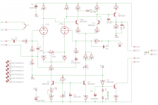
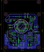
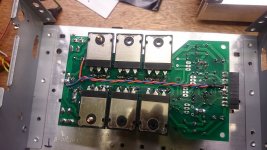
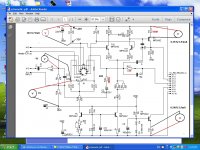
Here schematic with double triode in place....values are these from 12UA7 borys one....and the layout for octal double triode=>6sn7. Goal is +/-45-50Vdc rail direct Cap multiplier pn OPS board
Here schematic with double triode in place....values are these from 12UA7 borys one....and the layout for octal double triode=>6sn7. Goal is +/-45-50Vdc rail direct Cap multiplier pn OPS board
Attachments
Last edited:
Marc! Nice website, you have built a lot of amps, BUT NO NAKSA!!
Hugh
Yes hugh never build one as it's a finish product => amp module. I like a lot the VSSA lazy moudul sound but no fun to buil....just case and wiring job....so not funny for me. I like playing with routnig soft and have the result in my end after etching....This way i can arrange the project to my desire as i do for Quasi Nbip and vesatil project. I just need a proof schematic to 36 or 50V rail (PSU i have in stock) to play with.
Marc
Hi idefixes,a jpg or pdf pcb will be more useful😉Hugh
Here schematic with double triode in place....values are these from 12UA7 borys one....and the layout for octal double triode=>6sn7. Goal is +/-45-50Vdc rail direct Cap multiplier pn OPS board
Hi idefixes,a jpg or pdf pcb will be more useful😉
I will give it as ECC88 one, but just need some one to validate schematic to be sure it's viable, than you can have pdf, gerber, jpeg, mirrored or not...
Marc
Idefixes
I do not know a lot about the tubes but for sure there is a difference in between them, I have old phillips e88cc and is working very badly in the circuit (I am getting overshoots like in Terrys scope readings) but if I will put JJ Tesla e88cc tube (brand new one, not old stock) all is perfect. This is the problem I think, the only solution I see there is to use exacly same new tube or change design a little to leave big safety margin. Compromises everywhere.
If someone can suggest a tube which can work ok with low anode voltage I can get one and give it a another try, but tube must be new and easy availible like 12au7 and e88cc (most popular and easy availible).
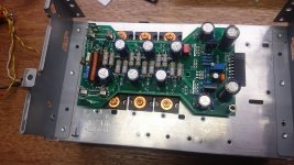
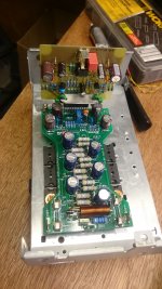
I have to finish up the enclosure to do some further work on the amp, a lot of listening tests.
I do not know a lot about the tubes but for sure there is a difference in between them, I have old phillips e88cc and is working very badly in the circuit (I am getting overshoots like in Terrys scope readings) but if I will put JJ Tesla e88cc tube (brand new one, not old stock) all is perfect. This is the problem I think, the only solution I see there is to use exacly same new tube or change design a little to leave big safety margin. Compromises everywhere.
If someone can suggest a tube which can work ok with low anode voltage I can get one and give it a another try, but tube must be new and easy availible like 12au7 and e88cc (most popular and easy availible).
I have to finish up the enclosure to do some further work on the amp, a lot of listening tests.
Attachments
If someone can suggest a tube which can work ok with low anode voltage I can get one and give it a another try, but tube must be new and easy availible like 12au7 and e88cc (most popular and easy availible).
I have to finish up the enclosure to do some further work on the amp, a lot of listening tests.
Using 22kohm anode resistor makes the whole thing very complicated, as the anode voltage will be around 30V with 1mA anode current. Almost no valve, which can accept such a low voltage. Maybe ECC86 can do it, but it's hard to find.
Sajti
sajti
The anode load resistors can be lowered and current increased a bit just in case.
As far I know the grid must be positive biased (vs cathode) so there is no way around, anode resistors/bias and grid voltage are all dependend.
The anode load resistors can be lowered and current increased a bit just in case.
As far I know the grid must be positive biased (vs cathode) so there is no way around, anode resistors/bias and grid voltage are all dependend.
The grid must be negative biased comparing to the cathode. I see schematic with 4.7kohm anode resistor. That looks much better to me.
Sajti
Sajti
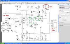
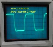
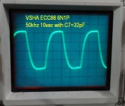
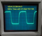
Some measurements and a scope test.
Yellow signal is the input voltage
Blue signal is output voltage.These for first picture.
In 2nd picture(opposite colors) signal levels are just before clip.
So an inp. signal about 541mV gives 28.6v RMS out on a 6R load =136W RMS(before clip) ,or 204W RMS/4R(+/-50V POWER SUPPLY)
Yellow signal is the input voltage
Blue signal is output voltage.These for first picture.
In 2nd picture(opposite colors) signal levels are just before clip.
So an inp. signal about 541mV gives 28.6v RMS out on a 6R load =136W RMS(before clip) ,or 204W RMS/4R(+/-50V POWER SUPPLY)
Attachments


Last edited:
Terry
I am using JJ (Tesla) E88CC tubes and they fit in just perfect, unfortunatly the tube tolerances arent so good. To get rid of overshoot the easiest way is to increase compensation cap from VAS to NFB (5pF) but in Spice Bode plots are not so good.
So plan B is:
-Increase R3=47R VAS resistor to 100R
-Place 100pF capacitor across R33=100kR
-do the square tests
thimios
Exacly the gain must be lowered somwhere, VAS current should be roughly the same, the CCS pulls the active VAS transistor.
Regards
Hi Peter,
This is what I have tried so far. Marc had already included C9 (100pF) across R33 so that was in place. I lifted it but no change. Next I added 10pF to C7, (I had 6pF there), so now I have 16pF. I see a very small change. So I add 33pF instead of the 10pF. The over shoot is gone but the square waves are looking rounded at 20khz. So next I pull C7 and install 33pF only. This is the best so far. The top of the square wave looks good but the bottom still has a slight over shoot. It's probably fine like this but maybe you have an idea how to make them both look the same.
EDIT: I just changed R3 to 100R and now the bottom of the wave is flat but the top is slightly rounded. Maybe I need to reduce C7?
Blessings, Terry
Attachments
Last edited:
Ok, I tried a few more things. I changed R3 to 150R. Now the top and bottom waves look the same but the bottom wave is less voltage. I tried reducing C7 to 27pf but the overshoot comes back when pushed past 10vac output. So far the best looking waves are with R3=150R and C7=33p. This is with 6n1P.
Blessings, Terry
Blessings, Terry
thimios
I have updated the schematic few posts ago to increase the safety margin, I think Terry have made a changes, increse the two resistors marked in green and replace red 47R resistor with 100R.
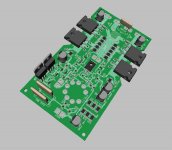
The small OPS is nearly done, just few bits and pieces left..
Regards
Peter, this is cool - I have recently come to the same kind of shape without seeing yours 😀

Attachments
- Home
- Amplifiers
- Solid State
- Very Simple Hybrid Ampifier