Terry
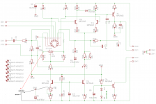
The black meter probe to GND and red to top of the one of 470R degeneration resistors at LTP. Voltage must be positive and value approx 0,9V (In my case), basically you can set it from 0,5V to 1,5V with listening tests what would be the best for you.
Hugh
I will try to make a tube VAS with CCS later on but now I will have to finish speakers with big woffers.
Regards
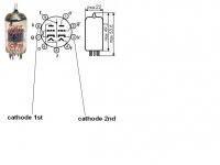
Sorry, I don't know what you mean by the top of the resistors. Do you mean at pin 3 and/or pin 8 or where the resistors tie together? I wasn't aware this amp had an LTP.
Last edited:
Sorry, I don't know what you mean by the top of the resistors. Do you mean at pin 3 and/or pin 8 or where the resistors tie together? I wasn't aware this amp had an LTP.
Attachments
Today i have an accident with mine valve IPS.
Testing this with low level out(square wave 800mv 1Khz)on a 4R SPEAKER ,ended up with a smoked 2sa1943 out trans.🙁
I'm afraid that this isn't a stable IPS.
Testing this with low level out(square wave 800mv 1Khz)on a 4R SPEAKER ,ended up with a smoked 2sa1943 out trans.🙁
I'm afraid that this isn't a stable IPS.
thimios
On the screan above the black meter probe must be putted to GND not to the negative rail.
The valves gain tolerance is quite wide so overal ips gain can be vary a bit.
I am playing with that IPS (3 pieces all together) with no issues for good few months.
R3=47R increase to 100R.
Tell me please which IPS was connected with ecc88 or with ecc82 ??
If you have had a problem with ecc82 IPS try to connect the compensation cap from VAS
Oh sorry it is late for correction🙁thimios
On the screan above the black meter probe must be putted to GND not to the negative rail.
The valves gain tolerance is quite wide so overal ips gain can be vary a bit.
I am playing with that IPS (3 pieces all together) with no issues for good few months.
R3=47R increase to 100R.
Tell me please which IPS was connected with ecc88 or with ecc82 ??
If you have had a problem with ecc82 IPS try to connect the compensation cap from VAS
What a big mistake🙁
Borys. I'm playing this for days without issue but when testing this with A.F generator on a real 4R (800mV OUTPUT ONLY)speaker, the damage occurred.
Please ATTENSION post #223 wrong schematic
This one is correct.
Attachments

Last edited:
thimios
Please let me know which version you have the problem with, the 12AU7 tube based on ??
If yes the tube might have too much gain and it can be reduced by replacement just a few resistors. Please post your current schematic Ill tell U what to change.
Please let me know which version you have the problem with, the 12AU7 tube based on ??
If yes the tube might have too much gain and it can be reduced by replacement just a few resistors. Please post your current schematic Ill tell U what to change.
Hi borys .I'm using this versionthimios
Please let me know which version you have the problem with, the 12AU7 tube based on ??
If yes the tube might have too much gain and it can be reduced by replacement just a few resistors. Please post your current schematic Ill tell U what to change.
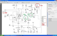
My power supply is +/-50v ,keep in mind that the accident occurs when out voltage was 800 mv only
This IPS start to clip with an input at about 650mV RMS.
Attachments

Last edited:
thimios
I have updated the schematic few posts ago to increase the safety margin, I think Terry have made a changes, increse the two resistors marked in green and replace red 47R resistor with 100R.
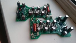
The small OPS is nearly done, just few bits and pieces left..
Regards
I have updated the schematic few posts ago to increase the safety margin, I think Terry have made a changes, increse the two resistors marked in green and replace red 47R resistor with 100R.
The small OPS is nearly done, just few bits and pieces left..
Regards
Attachments
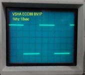
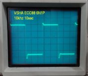
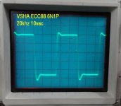
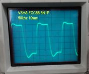
OK I have the ECC88 board playing. There is a little overshoot. Maybe this circuit doesn't like the 6N1P. It plays fine and sounds good. Here are some things I noticed that may lead to some clues.
1) The two tubes are not equal. To get equal voltage at the cathodes I have 4.3V at the collector of T5 on one tube and 5.2V on the other tube. This gives about .68V at the cathodes.
2) If I go more than .7V on the cathode the offset won't settle.
Here are some scope shots
1) The two tubes are not equal. To get equal voltage at the cathodes I have 4.3V at the collector of T5 on one tube and 5.2V on the other tube. This gives about .68V at the cathodes.
2) If I go more than .7V on the cathode the offset won't settle.
Here are some scope shots
Attachments
lower gain and vas current😉thimios
I have updated the schematic few posts ago to increase the safety margin, I think Terry have made a changes, increse the two resistors marked in green and replace red 47R resistor with 100R.
The small OPS is nearly done, just few bits and pieces left..
Regards
Nice baby OPS!
Terry
I am using JJ (Tesla) E88CC tubes and they fit in just perfect, unfortunatly the tube tolerances arent so good. To get rid of overshoot the easiest way is to increase compensation cap from VAS to NFB (5pF) but in Spice Bode plots are not so good.
So plan B is:
-Increase R3=47R VAS resistor to 100R
-Place 100pF capacitor across R33=100kR
-do the square tests
thimios
Exacly the gain must be lowered somwhere, VAS current should be roughly the same, the CCS pulls the active VAS transistor.
Regards
Peter, Terry, Thimios,
Try listening; do you think that the ECC88 is superior to the 12AU7? If not, maybe the original is the better; less loop gain, probably by quite a dB. The 12au7 has mu of 20, the ECC88 is 33, but its less than half rp of the 12AU7 (6.5K) and the loading is very different too. To complicate things, the ratio of plate load to plate impedance is 3.3/6.5 = 0.5 (12AU7) and 4.7/2.75 = 1.7 (ECC88). This has profound on the sound quality because it affects the distortion profile. Lastly, the plate current is very small, and this increases the plate impedance hugely and therefore affects sound quality.
If more lag compensation is needed it indicates there is a lot more OLG, and loop gain too. The square wave indicates more compensation needed for the ECC88, as you say.
The question would be: do you prefer to listen to the 12AU7 rather than the ECC88, and if so, why. Another option might be to try a 6CG7, a closer tube to a 6SN7, on which the 12AU7 is based. The 6CG7 is reputed to be quieter and more linear....
Very nice amplifier, I do like it a lot.
Hugh
Peter, Terry, Thimios,
The question would be: do you prefer to listen to the 12AU7 rather than the ECC88, and if so, why. Another option might be to try a 6CG7, a closer tube to a 6SN7, on which the 12AU7 is based. The 6CG7 is reputed to be quieter and more linear....
Very nice amplifier, I do like it a lot.
Hugh
I agree with AKSA ECC82 is vell working in this amplifier. I vote to the 6SN7 as the best choice, even it is large.
If You keep the noval type the GE 5814a is very good version of ECC82. Another candidate is the Tungsram ECC82 which has good reputation around the tube diyers.
Sajti
These getting more and more interesting. I made the layout for the ECC88 type but I wait for further tests or improvement , rather say the final variation.
Also we need to acknowledge Terry use some type of Russia tube which is very likely not 100% equivalent to ECC88 family. Can someone check upon that..
The 6SL7 is great tube but is octal and much larger by size.
Sajti you always come up with excellent ideas.
Greetings
Also we need to acknowledge Terry use some type of Russia tube which is very likely not 100% equivalent to ECC88 family. Can someone check upon that..
The 6SL7 is great tube but is octal and much larger by size.
Sajti you always come up with excellent ideas.
Greetings
The question would be: do you prefer to listen to the 12AU7 rather than the ECC88, and if so, why. Another option might be to try a 6CG7, a closer tube to a 6SN7, on which the 12AU7 is based. The 6CG7 is reputed to be quieter and more linear....
Very nice amplifier, I do like it a lot.
Hugh
Hi hugh,
I a quite bunch far to be a spécialist, just an humble builder...but i don't have in mind a desgn were 6SN7 is use with such low rail voltage as +/-50Vdc...I have some 6sn7 laying around and if the design could macth the case of not using HT more power supply i would take a try. Space is not a big deal to me.
Marc
Peter, Terry, Thimios,
If more lag compensation is needed it indicates there is a lot more OLG, and loop gain too. The square wave indicates more compensation needed for the ECC88, as you say.
Hugh
Another idea for ECC88: Increase the cathode resistors. For first seen I would double them. R10->2kohm R16, R17->1kohm. This will reduce the higher OLG resulted by the ECC88.
The low voltage application needs lot of compromise for the tubes. The ECC88 has somewhat better (measured) performance with low voltage operation.
Sajti
Hi hugh,
I a quite bunch far to be a spécialist, just an humble builder...but i don't have in mind a desgn were 6SN7 is use with such low rail voltage as +/-50Vdc...I have some 6sn7 laying around and if the design could macth the case of not using HT more power supply i would take a try. Space is not a big deal to me.
Marc
6SN7 will work with 50V anode voltage. The only issue is the reduced anode current. Checking the characteristics maximum of 5mA is available. I would not use it with more than 2mA to avoid the saturation/overdriving.
Sajti
- Home
- Amplifiers
- Solid State
- Very Simple Hybrid Ampifier