bimo,did you see post#142?
No, I'm sory. I look at Bory's measurement at the begining of this thread.
Bimo, at the begining of this thread is another IPS+OUTPUT not this last version.No, I'm sory. I look at Bory's measurement at the begining of this thread.
This last version is an IPS only,a general IPS.
I never built the,borys output stage.I tried this IPS in conjunction with Ostriper output stage(Slewmaster.)
Last edited:
Bimo, at the begining of this thread is another IPS+OUTPUT not this last version.
I sim the post #69 IPS with Ostripper OPS (3EF).
Do you mean high bandwidth amplifier will be better?
This is the result of low phase shift.... yes, you are right!
Hugh
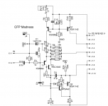
Another good suprise IPS is CFP one, only 6 transistors with singleton input. Plays lovley. I was going to putt the servo into it but Valery came up with some better idea so i have adopted it. Offset is not so bad, sound is really nice. Schematic bellow.
I agree. I built this little postage stamp IPS. Very nice
Where we can find this IPS pcb?Another good suprise IPS is CFP one, only 6 transistors with singleton input. Plays lovley. I was going to putt the servo into it but Valery came up with some better idea so i have adopted it. Offset is not so bad, sound is really nice. Schematic bellow.
Peter,
You are very creative, but you have been off on a tangent with a new 'madness' amp!!
Why are you ignoring your older design, your hybrid is wonderful, would you consider refining it further? Maybe a few other tubes?
I ask because I know Terry likes it very much and he has built more amps than I have had hot dinners....... I'm not particularly well, and my input is restricted to comments from the sidelines, otherwise I would be building it too. But I'm selfish, I want smart guys like you, Thimios, Terry and Bimo to build the best amp in the world - with a wacky, unconventional design.
Ciao
Hugh
Hi Peter,
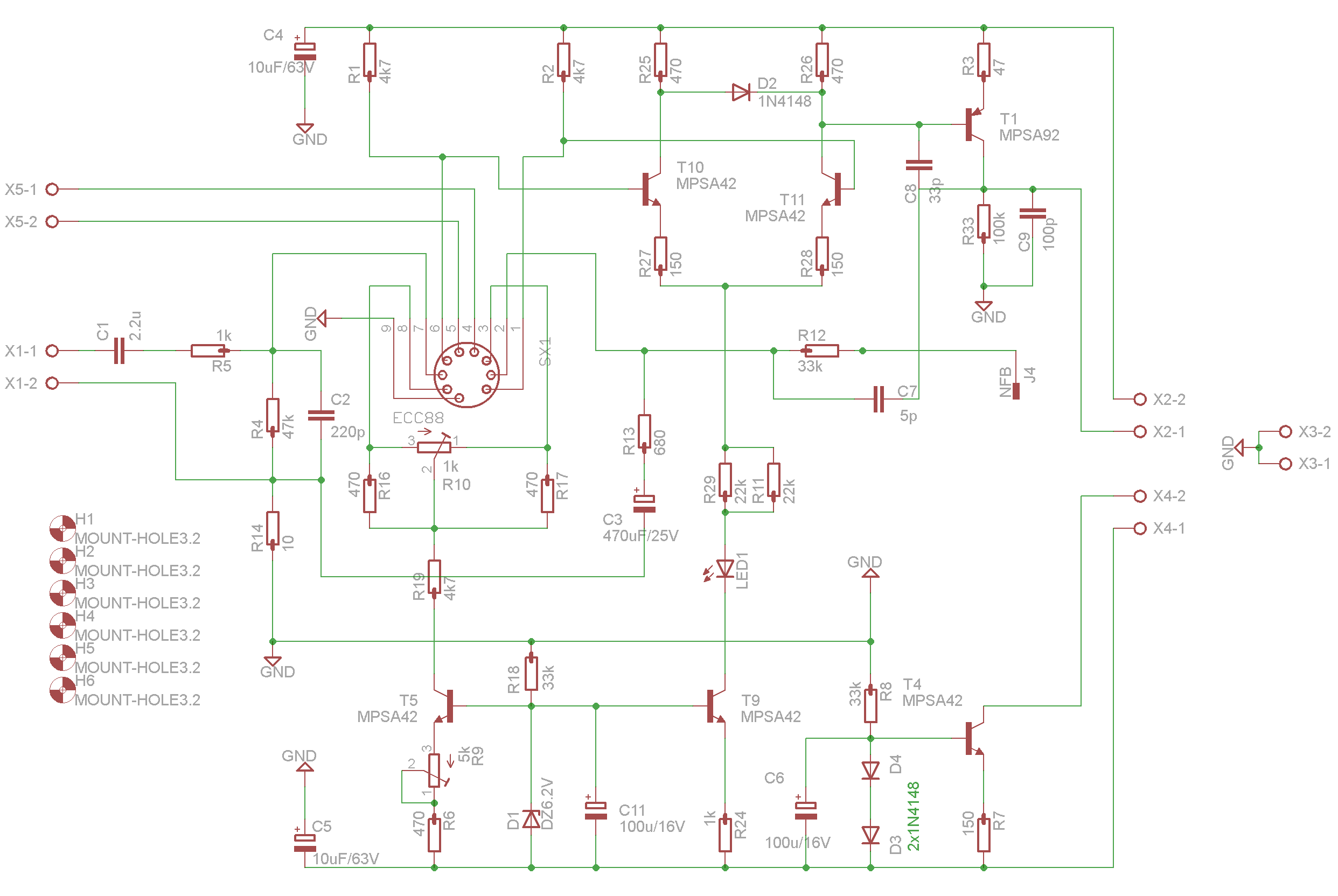
My tubes arrived for the ECC88 boards. They are the 6N1P tubes. I'm looking back through the thread and I don't see instructions for setting R9 trimpot. Can you explain that for me please?
Thanks, Terry
My tubes arrived for the ECC88 boards. They are the 6N1P tubes. I'm looking back through the thread and I don't see instructions for setting R9 trimpot. Can you explain that for me please?
Thanks, Terry
I don't think the 6N1P (6N1P-EV, Voshod?) is the equivalent to the ECC88 (6DJ8, etc) but rather the 6BQ7A or 6N23 - Not too sure - something about the tube's gain and the heater current?
Hi Hugh, good to see your health continues to improve
Yes, how about the 'good ol' 6C45' that Andrea Ciuffoli uses, except you need 2 tubes - any twin triode equivalent?
Yes, how about the 'good ol' 6C45' that Andrea Ciuffoli uses, except you need 2 tubes - any twin triode equivalent?
Hi Peter,
My tubes arrived for the ECC88 boards. They are the 6N1P tubes. I'm looking back through the thread and I don't see instructions for setting R9 trimpot. Can you explain that for me please?
Thanks, Terry
I found it is difficult to set DC Offset in simulation. First, I set R9 to get minimum DC Offset, but some value the DC offset can go as high as PSU voltage.
I found it is difficult to set DC Offset in simulation. First, I set R9 to get minimum DC Offset, but some value the DC offset can go as high as PSU voltage.
I'm using this schematic. I think R9 sets the current and R10 sets the offset. One board is working OK but the other is not.
R9 sets the I cathode and R10 the out offset.I'm using this schematic. I think R9 sets the current and R10 sets the offset. One board is working OK but the other is not.
I tried two tubes.One used 12AU7 and one new ECC82.Using the 12AU7 i ended with 33mV offset,Using ECC82 the offset it is possible to trim at 0mV offset.
My board is according to previous version.
R9 sets the I cathode and R10 the out offset.
I tried two tubes.One used 12AU7 and one new ECC82.Using the 12AU7 i ended with 33mV offset,Using ECC82 the offset it is possible to trim at 0mV offset.
My board is according to previous version.
Hi Thimios,
I already have the original boards working perfectly. These are the ones designed for the ECC88 tube. What I want to know is how to set R9. I don't know where to measure and what voltage to set it to.
Measure cathode voltage..It the is point connection of R10 R16Hi Thimios,
I already have the original boards working perfectly. These are the ones designed for the ECC88 tube. What I want to know is how to set R9. I don't know where to measure and what voltage to set it to.
Last edited:
- Home
- Amplifiers
- Solid State
- Very Simple Hybrid Ampifier