Terry
The LEDs in the A9 are only for information that current is flowing, U can putt your's favorite colour there. VSSA is great amp in high octave.
sajti
I must get that LM4562 to give it a try
Regards Peter
The LEDs in the A9 are only for information that current is flowing, U can putt your's favorite colour there. VSSA is great amp in high octave.
sajti
I must get that LM4562 to give it a try
Regards Peter
Up to now i can't be sure,but this valve IPS is very promising!Valery,
Thanks for the post! I'm with you, the 12AU7 is a ruggedized 6SN7/6CG7, and works well down to very low Ik and Vak. The Ongaku used a 6SN7 input stage SRPP at 105V! I suggest 6DJ8/ECC88 because it's even lower and it's rp is less than half of the 12AU7, so necessary with very low plate loading. You'd probably want to reduce the 3k3 loads down to around 1k, but I'd suggest a larger Ik, say around 5mA? However, Terry and Peter have the proto and I leave it to them. I have less energy to undertake wonderful designs these days, but I have built a tube into a GNFB network some years back and it was extremely successful sonically. Wonderful tube sonics, and incredible bass and depth of image.
Hugh
Vssa valve in same boat with slewmaster.
Good job borys congratulation!
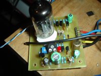
A good friend make me an offer ,a genuine old 12au7 made in U.S.A ,so i couldn't resist to curiosity.
From a small listening test...strong clear bass and wonderful crystal treble
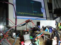
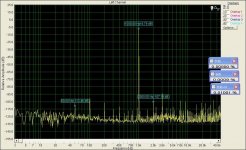
A small measurement test.
Please don't take measurement numbers as accurate.This is what my sound card can measure.
In this first test filaments power supply is switch mode type.
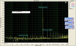
There is a little hum,so i tried to gnd one pole of filament.
Picture no 5 is without filament gnd when picture no 6 is with filament gnd.
Offset is about 33mV
Attachments

Last edited:
timios
Nice job!!!
Some of the artefacts in measurements --> all electronics at home/lab is connected with centre pin to GND so please try to disconnect scope from output (its GND is connected to to the mains centre earth pin).
I have to try the ecc88 as it is a preamp tube.
The filament supply can be symetrised, if you put two resistors in series in between the wires (let me say 220R or 470R) and put centre resistor connection to GND.
You can try to adjust some differend cathode voltages, from 0,5V up to 1,5V the thd profile is changing a bit and the sound prapobly too.
Filament----470R------GND------470R------Filament
Regards Peter
Last edited:
try to disconnect scope from output (its GND is connected to to the mains centre earth pin).timios
Nice job!!!
Some of the artefacts in measurements --> all electronics at home/lab is connected with centre pin to GND so please try to disconnect scope from output (its GND is connected to to the mains centre earth pin).
I have to try the ecc88 as it is a preamp tube.
The filament supply can be symetrised, if you put two resistors in series in between the wires (let me say 220R or 470R) and put centre resistor connection to GND.
You can try to adjust some differend cathode voltages, from 0,5V up to 1,5V the thd profile is changing a bit and the sound prapobly too.
Filament----470R------GND------470R------Filament
Regards Peter
I can't understand what you mean.I haven't any scope connected to output.Can you explain more?
thimios
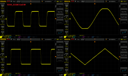
That is OK.
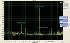
I have my scope connected to the output to check what amplitude I have when I am takeing FFT measurements, and when scope is connected I am getting similar artefacts at the FFT spectrum (kind of tall grass). So to get rid of the artefacts I am connecting the scope threw a resistor. Looks like PSU in your PC is not the highest quality (or soundcard).
That is OK.
I have my scope connected to the output to check what amplitude I have when I am takeing FFT measurements, and when scope is connected I am getting similar artefacts at the FFT spectrum (kind of tall grass). So to get rid of the artefacts I am connecting the scope threw a resistor. Looks like PSU in your PC is not the highest quality (or soundcard).
I can't believe that is a problem with pc or sound card because measuring other IPS like IPS Eyesse those artifacts don't exist.thimios
That is OK.
I have my scope connected to the output to check what amplitude I have when I am takeing FFT measurements, and when scope is connected I am getting similar artefacts at the FFT spectrum (kind of tall grass). So to get rid of the artefacts I am connecting the scope threw a resistor. Looks like PSU in your PC is not the highest quality (or soundcard).
Attachments
thimios
Please try to make FFT more readable, there is so many products at fft grass so it is hard to say where they comming from. It is hard to belief that amp is producing so high order harmonics (I could be wrong too).
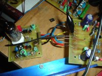
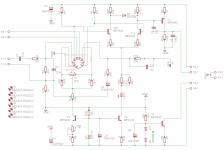
Small update about VSHA, I have made few minor changes and tryed ECC88 and must say it sounds even better than ECC82 (12AU7) in my case, there is more ''taste'' in the top octave. I have some work left to do with it to chose the best config. The hum spikes are nearly gone (prapobly thanks to the pin 9 in ecc88).
Current schematic and few postcards bellow.
Please try to make FFT more readable, there is so many products at fft grass so it is hard to say where they comming from. It is hard to belief that amp is producing so high order harmonics (I could be wrong too).
Small update about VSHA, I have made few minor changes and tryed ECC88 and must say it sounds even better than ECC82 (12AU7) in my case, there is more ''taste'' in the top octave. I have some work left to do with it to chose the best config. The hum spikes are nearly gone (prapobly thanks to the pin 9 in ecc88).
Current schematic and few postcards bellow.
Attachments

What were the minor changes you made? I really like this IPS. I too would like to try the ECC88.
Very nice Peter
Hopefully it will be layout for the ECC88 tube .
It has different pin out than the ECC82. For some reason more popular tube...
One of my favorite D3a tube Siemens
Greetings Gabor
Hopefully it will be layout for the ECC88 tube .
It has different pin out than the ECC82. For some reason more popular tube...
One of my favorite D3a tube Siemens
Greetings Gabor
Very nice Peter
Hopefully it will be layout for the ECC88 tube .
It has different pin out than the ECC82. For some reason more popular tube...
One of my favorite D3a tube Siemens
Greetings Gabor
Something like this....
Attachments
Last edited:
Bummer. I didn't realize that the ECC88 had a different pinout than the 12AU7. I was hoping I could just swap them out. Looks like I'm going to have to etch some more boards. 😀 Unfortunately Idefixes board is two layer. Beautiful for board house boards but too difficult for me to etch.
Blessings, Terry
Blessings, Terry
Thank you Mark nice work but the to produce professionally. OK I do not mind to order boards if there will be some GB.
These not a heat transfer friendly version. Again look great, we appreciate your effort.
Thank you one more time!
Greetings
These not a heat transfer friendly version. Again look great, we appreciate your effort.
Thank you one more time!
Greetings
Bummer. I didn't realize that the ECC88 had a different pinout than the 12AU7. I was hoping I could just swap them out. Looks like I'm going to have to etch some more boards. 😀 Unfortunately Idefixes board is two layer. Beautiful for board house boards but too difficult for me to etch.
Blessings, Terry
To me to 😀😱
Lets hope someone will organise a small GB.
These nice and compact size.🙂
Greetings
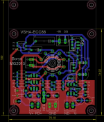
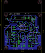
So for home etching...same with juste 2 jumper
Attachments
Last edited:
Perfect! can you please post Sprint file or at least PDFs for etching and maybe a mirror of the silk?So for home etching...same with juste 2 jumper

Marc
Nice job!!
Just small info, the ECC88 version I have used slightly differend compensation, C7 cap is not across nfb resistor, it is going from NFB network to active VAS side. Please correct the connection on the board or make the room on the board for another one (I will check later where to put it, few more tests required)
Terry
The changes to fitt ecc88 are as fallows:
1. 22kR LTP resistors ----> 4,7kR
2. Filament connected in between pin 4 and pin 5 of tube socket.
3. Pin 9 of tube connected to GND
4. Compensation cap 5pF connected from NFB divider to VAS
5. 22kR resistor from CCS replaced with 10kR.
I will try a few more variants and post results.
Regards Peter
Last edited:
I will try a few more variants and post results.
Regards Peter
Thank you Peter.🙂
Hi Mark,
I do iron transfer so I need mirror silk and straight bottom. Looks like you have mirror bottom and straight silk.
Thanks, Terry
I do iron transfer so I need mirror silk and straight bottom. Looks like you have mirror bottom and straight silk.
Thanks, Terry
- Home
- Amplifiers
- Solid State
- Very Simple Hybrid Ampifier