thimios
Wow
So quick, well done!!
If the amps is running I am very happy.
Looking forward some listening impressions.
thx
Peter
Wow
So quick, well done!!
If the amps is running I am very happy.
Looking forward some listening impressions.
thx
Peter
Hi Peter🙂thimios
Wow
So quick, well done!!
If the amps is running I am very happy.
Looking forward some listening impressions.
thx
Peter
I want to ask about led's color.I see your uses an orange and a green one?
How critical is this for cathode bias?
Last edited:
There is nothing critital about the LED, it is only present for fancy look threw the 9 pin socket (my ones have hole in the middle) at the tube, you can replace the led with the jumper.
The HD pcb has led with 5mA flowing threw it and is lighting up the tube from the bottom.
The HD pcb has led with 5mA flowing threw it and is lighting up the tube from the bottom.
Ok thanks.There is nothing critital about the LED, it is only present for fancy look threw the 9 pin socket (my ones have hole in the middle) at the tube, you can replace the led with the jumper.
The HD pcb has led with 5mA flowing threw it and is lighting up the tube from the bottom.
What about 6n16 version?I have some of them in order....
6n16b version names VSHA_HD V5 and all stuff is in post #39.
The one thing I can say to compare two HD versions (the 12au7 and 6n16B) that version with miniature tube has a bit less top octave and less details than 12au7 one.
The one thing I can say to compare two HD versions (the 12au7 and 6n16B) that version with miniature tube has a bit less top octave and less details than 12au7 one.
Ok we can stay on 12au7.6n16b version names VSHA_HD V5 and all stuff is in post #39.
The one thing I can say to compare two HD versions (the 12au7 and 6n16B) that version with miniature tube has a bit less top octave and less details than 12au7 one.
Where is the pcb for HD version with 12au7?
Regards.
The HD version for 12au7 tube is bellow (same as post no #23), heater is 6.3V ac , but you can cut one track and make it for 12DC.
I didn't have any problems with it but had some with 6n16b tube and had to add another compensation cap.
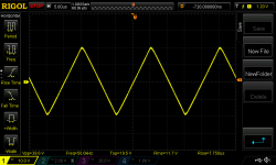
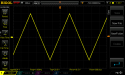
Just in case I have made a tests on v4 version too with additional miller cap at tranistor T1, amp is rock stable, no changes in performance.
Bellow few squares and triangles from it (2 x 47pF miller caps at the VAS stage)
I didn't have any problems with it but had some with 6n16b tube and had to add another compensation cap.
Just in case I have made a tests on v4 version too with additional miller cap at tranistor T1, amp is rock stable, no changes in performance.
Bellow few squares and triangles from it (2 x 47pF miller caps at the VAS stage)
Attachments


Last edited:
Hi Peter, from a short listening test i feel that low frequencies aren't deep .
What's your opinion bypass cathode resistors with capacitors?
What's your opinion bypass cathode resistors with capacitors?
Yes, the bass isnt the most powerfull but I am not sure how to improve it, or it is just the type of the mosfets used. There is quite a lot of second harmonic and maybe that is why the bass sounds like. I have never tryed to bypass the cathode resistors but I think is worth of trying.
Thanks for feedback, it is very important for me.
Try to bypass the input cap and do some listening tests again.
How does the simple version play above the bass range ??
Regards Peter
Thanks for feedback, it is very important for me.
Try to bypass the input cap and do some listening tests again.
How does the simple version play above the bass range ??
Regards Peter
Last edited:
Sorry i have the simple version only.Yes, the bass isnt the most powerfull but I am not sure how to improve it, or it is just the type of the mosfets used. There is quite a lot of second harmonic and maybe that is why the bass sounds like. I have never tryed to bypass the cathode resistors but I think is worth of trying.
Thanks for feedback, it is very important for me.
Try to bypass the input cap and do some listening tests again.
How does the simple version play above the bass range ??
Regards Peter
I have bypass the inp.capacitor .
or it is just the type of the mosfets used
Bass isn't deep with the VSSA (PMI version) also.(same fet pair).
Try with BJT.🙂 or with vertical fets.🙂
Last edited:
I have spotted that too, I have vssa and with single pair of latfets the bass isn't the strongest one but with IRFP the bass is really good. I have similar feedback from the few persons using latfets, middle and top octave beautiful but bass isn't the killer.
I will try hexfets later on, I have some BJT output stage to attatch so there is an option too.
Regards Peter
I will try hexfets later on, I have some BJT output stage to attatch so there is an option too.
Regards Peter
I have spotted that too, I have vssa and with single pair of latfets the bass isn't the strongest one but with IRFP the bass is really good. I have similar feedback from the few persons using latfets, middle and top octave beautiful but bass isn't the killer.
I will try hexfets later on, I have some BJT output stage to attatch so there is an option too.
Regards Peter
Hi borys, try to suppress on VSSA 10R/diode serie on each Vrail....
Marc
Hi Marc
I have tryed that trick too. I far I remember there was allways a diffrence in vssa circuit variants in bass area. With IRFP version the bass was able to crush the buildings 😛 , kind of had sounding with good kick. With latFET the bass was like sunday dinner, nice and tasty but not nasty.
I think I will try to put another pair of latfets and take listen to it, If it will not work I will solder good old horses IRFP.
Regards Peter
Waiting for results.Hi Marc
I have tryed that trick too. I far I remember there was allways a diffrence in vssa circuit variants in bass area. With IRFP version the bass was able to crush the buildings 😛 , kind of had sounding with good kick. With latFET the bass was like sunday dinner, nice and tasty but not nasty.
I think I will try to put another pair of latfets and take listen to it, If it will not work I will solder good old horses IRFP.
Regards Peter
Are these irfp240,9240 interchangeable without other changes?
Regards.
Thimios.
thimios
The Irfp are not interchangeable cause they need temp compensation and they have different pinout. Maybe I will prepare some more universal version so the BJT and mosfets can be soldered?
The Irfp are not interchangeable cause they need temp compensation and they have different pinout. Maybe I will prepare some more universal version so the BJT and mosfets can be soldered?
thimios
The Irfp are not interchangeable cause they need temp compensation and they have different pinout. Maybe I will prepare some more universal version so the BJT and mosfets can be soldered?
Ok we need a new pcb with vbe multiplier and pin rearrangement...
Peter, Thimios - your observation regarding weaker bass with Lateral FETs sounds odd to me 
My tests with 2-pairs LatFET OPS (part of TubSuMo) show excellent bass response. SlewMaster-based IRFP OPS is definitely more powerful with its 5 pairs of MosFets, but at the same volume LatFET OPS with 2-pairs (2SK1058/2SJ162) does not loose competition 🙄
Well, on the other hand, two pairs are two pairs 🙂 Maybe this is the difference 😛
Valery
Thanks for tip. The one renesas mosfet is only 7A, hmm I will maybe try the two pairs.
Advice me please , leave it as it is driven from dirrectly from the VAS or buffer it with another emiter fallower ? One pair is running fine with only 4.5mA biased VAS but two pairs I am not sure.
I am running the HD version with one pair latFETs right now, today I have compared it dirrectly with symasym (MJL4281/MJL4302) and there is not much difference in bass area (18cm wofer based monitors), with latFET version there is a bit less 50Hz and bellow but other than that is fine.
I will try something on next few days anyway.
THX
Peter
Bump.
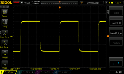
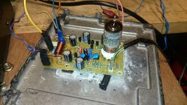
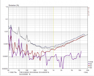
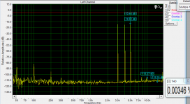
I have prepared another board (to be fitted flat with the heatsink), I did some minor changes + added emiter fallower just after VAS. Looks that there is some improvement made. The IMD products are gone, there is only 50/100Hz hum visible from my crap wiring setup 😛
I have some meas on my table with wires ect. but for now it looks like bellow.
No problems with bass either, very dynamic clear sound.
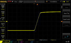
I have tryed to drive 2 pairs of LATfets dirrectly from 4,5mA VAS and didnt spotted any issues, squares were very clean without any signs of problems. Those transistors maybe are not the stronges ''horses'' but to drive them is very easy.
I think I must get some more voltage on the rails and try some 2 pairs as a next step.
Valery
To balance the mosfets capactance (RC's) I have used the 470R/330R. Would be correct way or maybe better use the same resistor values at the gates and put some small cap instead (like in Yours TuboSumo amp ??).
THX
BTW
I am listening the Dayton RS125 based monitors and must say this is my first Dayton and it is really awesome speaker !!
I have prepared another board (to be fitted flat with the heatsink), I did some minor changes + added emiter fallower just after VAS. Looks that there is some improvement made. The IMD products are gone, there is only 50/100Hz hum visible from my crap wiring setup 😛
I have some meas on my table with wires ect. but for now it looks like bellow.
No problems with bass either, very dynamic clear sound.
I have tryed to drive 2 pairs of LATfets dirrectly from 4,5mA VAS and didnt spotted any issues, squares were very clean without any signs of problems. Those transistors maybe are not the stronges ''horses'' but to drive them is very easy.
I think I must get some more voltage on the rails and try some 2 pairs as a next step.
Valery
To balance the mosfets capactance (RC's) I have used the 470R/330R. Would be correct way or maybe better use the same resistor values at the gates and put some small cap instead (like in Yours TuboSumo amp ??).
THX
BTW
I am listening the Dayton RS125 based monitors and must say this is my first Dayton and it is really awesome speaker !!
Attachments

Last edited:
- Home
- Amplifiers
- Solid State
- Very Simple Hybrid Ampifier