Terry
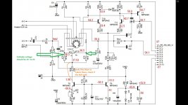
Looks like there is no current flowing threw the triodes. Please make sure the heater is connected (observe tube if it is starting to glowing after 5 seconds). On the top of the R16 and R17 resistors (cathodes ) there should be approx 1-2V.
I am currently working on that IPS, there will be some minor changes.
Hi Borys,
The heater is good, tubes are warm. I'm not sure what you mean by " on top of R16 and R17. Is that where I am reading 38.3V?
Thanks, Terry
EDIT: Was this layout not built?
The heater is good, tubes are warm. I'm not sure what you mean by " on top of R16 and R17. Is that where I am reading 38.3V?
Thanks, Terry
EDIT: Was this layout not built?
Last edited:
The picture will explain better than me.
This layout is build but only with BJT OPS, very simple very basic. With mosfet I used different VAS - same as symasym, and with fast mosfets is working perfect.
In Classic version there is simple transistor and CCS instead hitachi vas.
This layout is build but only with BJT OPS, very simple very basic. With mosfet I used different VAS - same as symasym, and with fast mosfets is working perfect.
In Classic version there is simple transistor and CCS instead hitachi vas.
Attachments
Last edited:
Hi Borys,
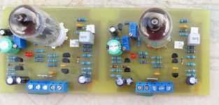
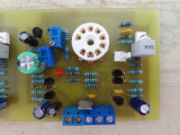
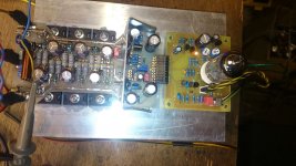
That is where I understood you say it. I checked all the values and they are correct. I'm attaching some pics. I am testing it with a Slewmaster mini OPS. This OPS works perfectly as I have been testing other IPS with it all week. Are you saying that you built this layout and it works with your BJT OPS? This is very strange.
BTW, I have it wired with the center terminal as ground and the spade feeding NFB so I can easily attach to the Slewmaster OPS.
Attachments
I have lost the ball?
Is this IPS the same posted in<<slewmaster builds>> thread?
Yes I think this is one of the three that Borys posted along with his little OPS.
I was able to get the other two working but this one just won't.
Last edited:
thimios
Yes this is the same IPS.
I just taken measurement from it bellow (15V).
Terry
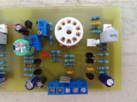
Please measure voltage across R19=22kR resistor (according to pic it is working ok 1,6mA) but where it goes. Than measure voltages across R1 and R2. Please check if R14=10R GND separating resistor is not blown. I am in lab now so will try to help. PS what tubes you have ??
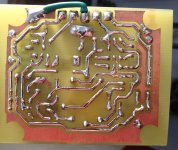
All looks soldered OK (my eyes hurts a bit).
Edit:
There is only one MPSA92 all others are MPSA42, just quick take a look please.
Edit2:
The LED orientation U can check with diode tester in meeter, but it is biassed up after the tube is on.
I am well puzzled.
Yes this is the same IPS.
I just taken measurement from it bellow (15V).
Terry
Please measure voltage across R19=22kR resistor (according to pic it is working ok 1,6mA) but where it goes. Than measure voltages across R1 and R2. Please check if R14=10R GND separating resistor is not blown. I am in lab now so will try to help. PS what tubes you have ??
All looks soldered OK (my eyes hurts a bit).
Edit:
There is only one MPSA92 all others are MPSA42, just quick take a look please.
Edit2:
The LED orientation U can check with diode tester in meeter, but it is biassed up after the tube is on.
I am well puzzled.
Attachments

Last edited:
I think you found it. I just checked and T1 is a MPSA42. Not sure how I missed that. It is midnight here so I will change that in the morning and retest.
Thanks
Thanks
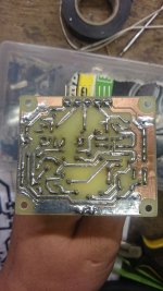
The marking on the MPSA92 and 42 are looking very same, I am soldering them other way around alll the time.
Borys what software used for this.thimios
Yes this is the same IPS.
I just taken measurement from it bellow (15V).
Terry
Please measure voltage across R19=22kR resistor (according to pic it is working ok 1,6mA) but where it goes. Than measure voltages across R1 and R2. Please check if R14=10R GND separating resistor is not blown. I am in lab now so will try to help. PS what tubes you have ??
All looks soldered OK (my eyes hurts a bit).
Edit:
There is only one MPSA92 all others are MPSA42, just quick take a look please.
Edit2:
The LED orientation U can check with diode tester in meeter, but it is biassed up after the tube is on.
I am well puzzled.
Is it Dr Jordan Design?
WOW!
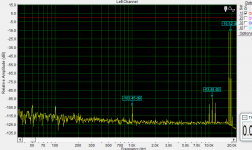
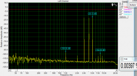
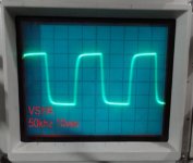
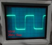
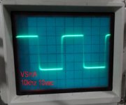
Love it! Plays beautifully. Offset settles quickly and holds solid. I didn't see a large offset at turn on. Less than 2V at switch on and settles at +-2mv. I have the cathode set to 1V. I am just playing it through the Slewmaster mini OPS at +-45V rails. Really, really nice sounding. I will hook it up to the A/B setup a little later and give a better comparison to some of my other amps. As for now I am very impressed.
Blessings, Terry
Attachments
-
 VSHA Classic V1 150khz.jpg46.8 KB · Views: 173
 -
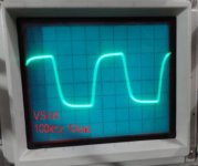 VSHA Classic V1 100khz.jpg45.1 KB · Views: 179
 -
 VSHA Classic V1 50khz.jpg47 KB · Views: 185
 -
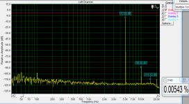
 VSHA Classic V1 20khz.jpg45.2 KB · Views: 545
 -
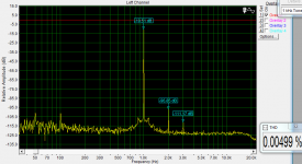
 VSHA Classic V1 10khz.jpg44.5 KB · Views: 536
 -
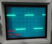 VSHA Classic V1 1khz.jpg45.4 KB · Views: 640
 -
 VSHA Classic V1 singing.jpg502.6 KB · Views: 677
 -
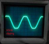 VSHA Classic V1 clipping.jpg43.7 KB · Views: 163
12ax7 will require 15 - 27k instead of 3.3k anode resistors and same value added to constant current leg.
Terry
I am happy to see it is working. It is very simple and basic amp (classic). I like it too.
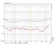
Clipp is nice and not sticking, squares looks good too. I am going to add one 100pF cap just in case because of input tupe tolerances (they all are not the same).
Kokanee
It is a rigol 4 channel, I forgotten the model, post it later when I am back at work.
thimios
Check PW please.
THX
I am happy to see it is working. It is very simple and basic amp (classic). I like it too.
Clipp is nice and not sticking, squares looks good too. I am going to add one 100pF cap just in case because of input tupe tolerances (they all are not the same).
Kokanee
It is a rigol 4 channel, I forgotten the model, post it later when I am back at work.
thimios
Check PW please.
THX
I have stuffed enclosure with all pcb's psu's etc, so my hybrid is up and running, but it needs a small update, I will have to add a V bias generator to compensate drivers Vbe, becouse I do not like to wait for bias to climb up.
Other than that amp is playing nice enough to bring it back home from the workshop.
Amazing job Peter. 🙂
- Home
- Amplifiers
- Solid State
- Very Simple Hybrid Ampifier